INTEGRATING THE EF2280 INTO YOUR SYSTEM
VORTEX EF2280 Reference Manual 38 Technical Support: 800.765.9266
selves, denoted as WM0, WM1, and WM2 are mixes that are input into the
main matrix. The “M” denotes Mix.
The P Bus. The P Bus is provided specifically to allow devices to share dig-
ital phone audio from the EF2241, EF2201, or EF2211. These devices can
both transmit and receive signals on the P bus, while the EF2280 can only
receive signals from the P bus.
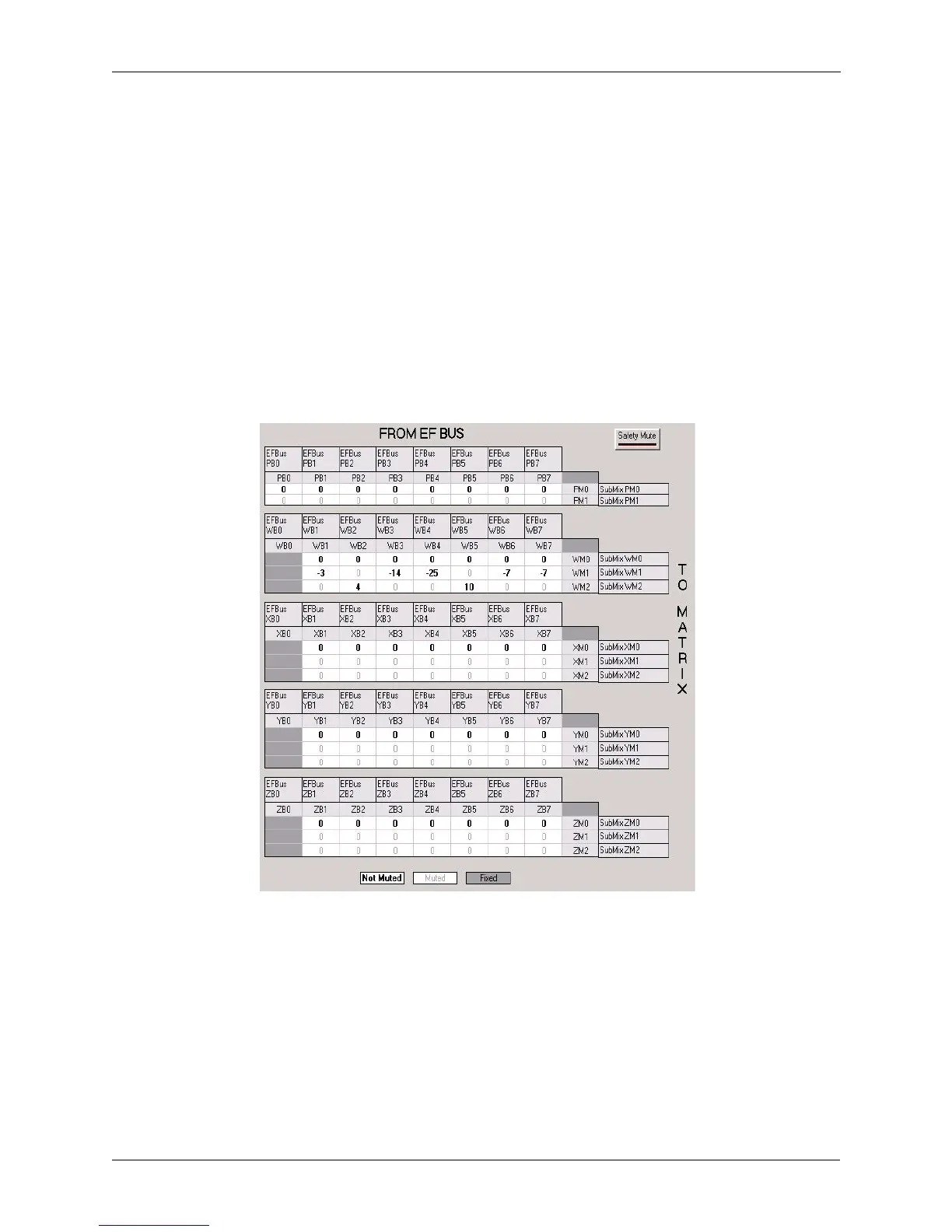
Crosspoint Mix Minus Bus. Each Vortex device in the system can
create four output mixes (W, X, Y, and Z) and place them on the bus. Each
device also can create three input mixes each from the W, X, Y, and Z busses
of the other devices (for a total of 12 mixes). The mixes can have crosspoint
gains on the signals from the other devices. See Figure 26 below. All 12 mixes
become inputs to the main matrix and can be mixed with the other inputs to
create outputs 1-8, A-D, Ref 1, Ref 2, and W, X, Y, and Z bus outputs.
EF Bus Reference. In a system with multiple devices, if all devices need
the same echo canceller reference, one device should be designated to put its
echo canceller reference (either Ref 1 or Ref 2) on the EF bus to be used as
the EF Bus Reference. All other devices
may use the EF bus reference as the
reference for their echo cancellers, or they can use their own internal refer-
ences. The references may include a mix of any input, with crosspoint gains,
including W, X, Y, and Z busses.
Figure 26. W, X, Y, and Z submatrices, and the P submatrix.