40 EGW06-PCPEG-20140813
TM
TM
Section IV: Installation
Sizing:
• The lines must be sized and routed so that oil is carried through the system. Using smaller lines than recommended
will give excessive pressure drops, resulting in reduced capacity and increased power consumption. Oversized lines
could result in an oil ow problem within the system and possible compressor damage.
• Excessive pressure drops in the liquid line may cause ashing of the refrigerant and a loss of a liquid seal at the
expansion valve inlet. A reduction in capacity may then occur because the presence of gaseous refrigerant will
partially block the expansion valve. Using hot gas and liquid line sizes recommended in the Air Cooled Condenser
section for these units and the proper system refrigerant charge will prevent this problem.
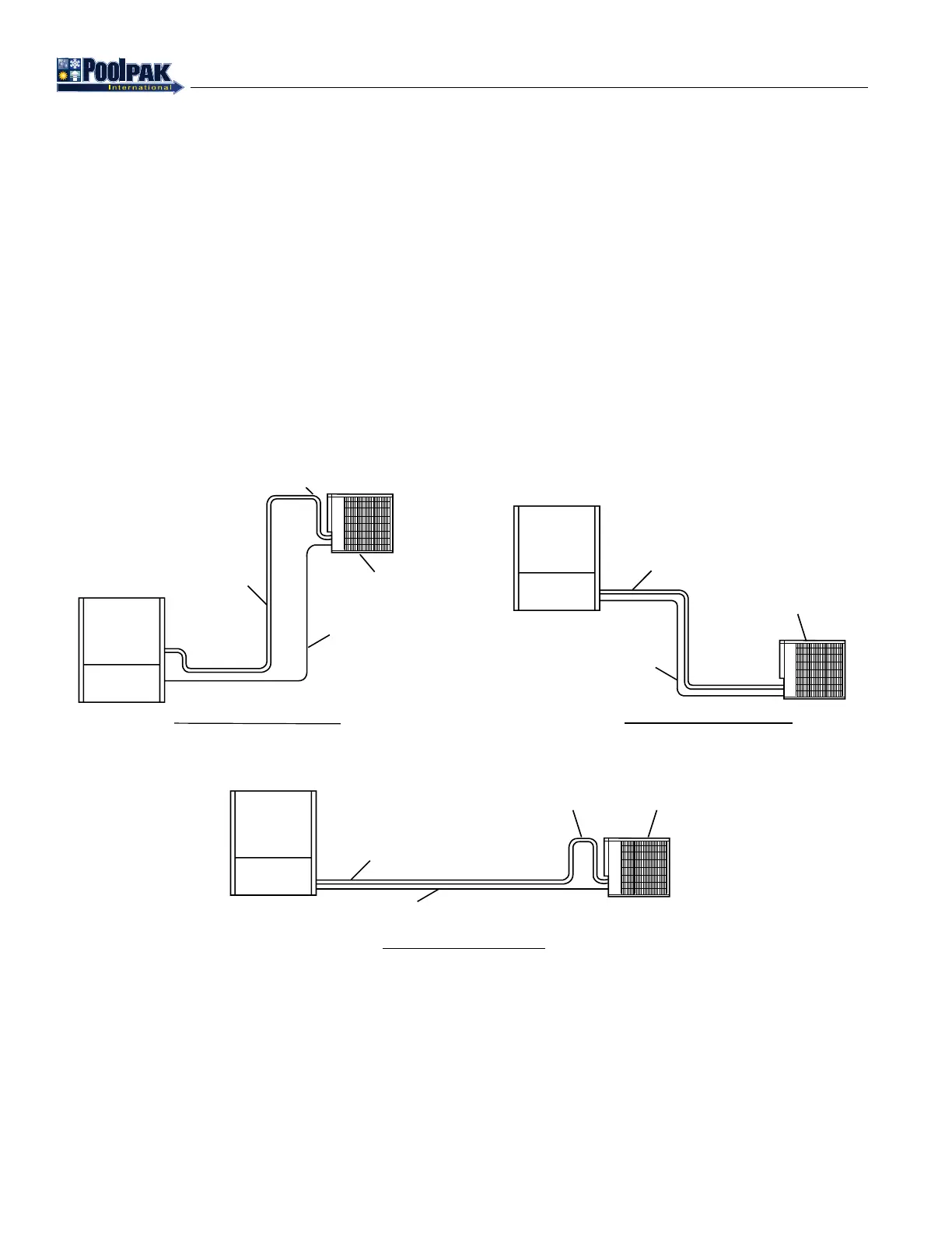
• Discharge lines should be designed to prevent condensed refrigerant and oil from draining back to the compressor
during OFF cycles. Use the following guidelines.
◦ The highest point in the discharge line should be above the highest point in the condenser coil.
◦ The hot gas line should loop toward the oor if the condenser is located above the PoolComPak™ unit, especially
if the hot gas riser is long.
• For refrigerant line sizing for an Air Cooled Condenser (ACC) where the lineset length is less than 100 feet or the
ACC location is less than 50 feet higher or 20 feet lower than the unit, use the below Table 4-3.
• ACC line lengths beyond the above limits will void warranty unless written approval is obtained from the
factory PRIOR to installation and startup.
Figure 4-14. ACC Refrigerant Piping
PCP_EG_ACCPiping_20140122.eps
DISCHARGE LINE
Pitch in
Direction of
refrigerant flow
LIQUID LINE
AIR-COOLED
CONDENSER
DISCHARGE LINE
Pitch in
Direction of
refrigerant flow
LIQUID LINE
AIR-COOLED
CONDENSER
TOP OF
CONDENSER
COIL
DISCHARGE LINE
LIQUID LINE
ACC LOCATED ABOVE
AIR-COOLED
CONDENSER
CONDENSER COIL
Pitch in
Direction of
refrigerant flow
ACC LOCATED BELOW
ACC LOCATED LEVEL