38
switch matrix it receives row and column inputs, responding when keys are pressed. It receives data
messages from the GPS receiver, and calculates and sends to the display GPS derived information. The
cpu pcb receives the outputs of the power supply and distributes power to the other boards. The analog
voltage proportional to received field strength from the receiver pcb drives lowpass active filters on the
cpu pcb, which are selected by the front panel LPF key to smooth the data. The selected filter output
feeds an analog-to-digital converter on the cpu IC from which the cpu generates the field strength value
directly in dBuV/m units, and from which it calculates field strength in voltage units. For reprogramming
the microcontroller in the field the pcb has a connector with cable attached which is accessed through the
PI 4100’s battery compartment.
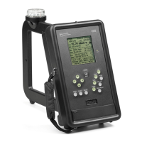
Display: The display pcb contains the liquid crystal display and its controller ICs. The display itself has
128x128 pixels and is backlighted by an array of LEDs.
GPS: The GPS pcb and its receiver module are products of the u-blox AG company, which is known for
its advanced GPS receiver ICs. The pcb is fed by a ceramic antenna located at the top of the PI 4100’s
case.
6.3 Printed circuit board drawings
Circuit schematic and component layout diagrams are shown on following pages for the CPU Board, the
Receiver Board, and the Power/Audio Board.