14
3.2 Primary Display Screen Elements
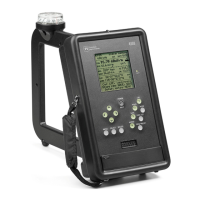
Refer to Figure 2 or to the PI4100 itself for the following discussion. Screen element descriptions are
given below with reference to horizontal lines of text, starting at the top with Line 1 and reading from
left to right in each line. For more detail on an item refer to Sec. 4, Operation.
Figure 2. PI 4100 Field Strength display
Line 1: Call sign of the selected station; Time and date from GPS (UTC + Offset).
Line 2: Frequency of the selected station; Modulation type; Battery voltage.
Line 3: Field strength value and units; Field strength trend indicator, points up for increasing, down
for decreasing field strength.
Line 4: Field strength value and units; LPF setting, degree of field strength smoothing, 1, 2, or 3;
internal temperature, ºC..
Line 5: Analog field strength indicator, each major division indicates 1 dB (12%) change.
Line 6: Bearing (magnetic) of the station from the PI4100; Azimuth of the PI4100 from the station.
Line 7: Distance of the PI4100 from the station; Internal correction value (for reference only)
Line 8: Latitude of the PI4100, degrees/minutes/seconds, from GPS.
Line 9: Longitude of the PI4100, degrees/minutes/seconds, from GPS; Number of GPS satellites in
view.
Lines 10, 11,12: Prompts for the operator, on manual self-calibration, storing a reading, and menu use.
Prompts vary with screen function.