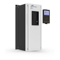
PART NAMES AND INSTALLATION
The CPU is not operating.
Flashing (1
second interval)
The communication module
is installed correctly in the
drive.
Communication between the
Communication module and
the drive is normal.
CPU and
ERROR
indicators flash
simultaneously
Communication error
occurred (no communication
is established) between the
communication module and
the drive.
CPU and
ERROR
indicators flash
asynchronously,
in 2 second
intervals
Abnormal communication
(failures) conditions exist
between the communication
module and the drive.
The communication module
failed to boot up.
LINK1 is connected to a
network.
LINK1 is not connected to a
network.
Network LINK1 is not
transmitting/receiving data.
Data transmission between
the Master unit and the
communication module is in
progress at network LINK1.
LINK2 is connected to a
network.
LINK2 is not connected to a
network.
Network LINK2 is not
transmitting/receiving data.
Data transmission between
the Master unit and the
communication module is in
progress at network LINK2.



 To Next Page