www.powerbox-systems.com
19
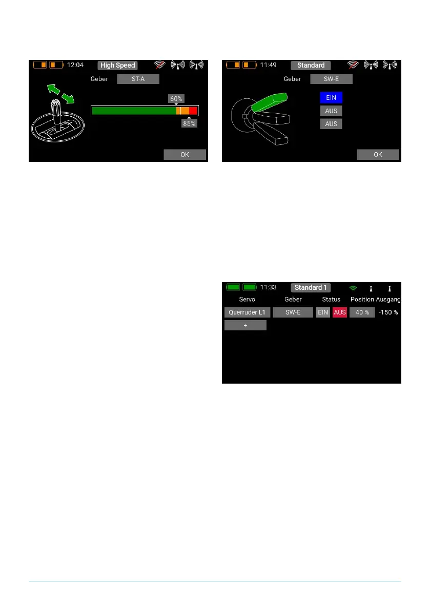
When you have selected a linear transmitter the two switching points can be placed in any position you like by
moving them with your nger. The red area indicates the “Off state”; the green area the “On state”. The orange
area indicates “hysteresis”, i.e. the area in which no switching takes place. You can very easily reverse the “Off
state” and the “On state” by moving one of the two switching point sliders in front of or behind the other.
This adaptability provides maximum exibility and simplicity, and you can immediately check the effect of your
settings by using the linear control. The transmitter control symbol on the left changes colour to indicate the
switched state.
If you wish to use a switch, you can very easily set the desired switch position to ON. If you select a 3-position
switch it is also possible to set two ON positions.
Press OK once you have completed your settings.
You are now returned to the Cut-Off function over-
view. Under Position set the servo position to which
the servo is to move when the transmitter control is
operated.
If the assigned transmitter control is set to off, the
servo output works as previously dened for that
function. As soon as the transmitter control is moved
to the ON position, the servo moves to the previously
dened position; you can read off the current value at
far right.
In the following section you will see your transmitter control on the left. Depending on whether you have selected
a linear input or a switch, you will see one of these screens: