32 PowerBox-Systems − World Leaders in RC Power Supply Systems
16. CONNECTIONS
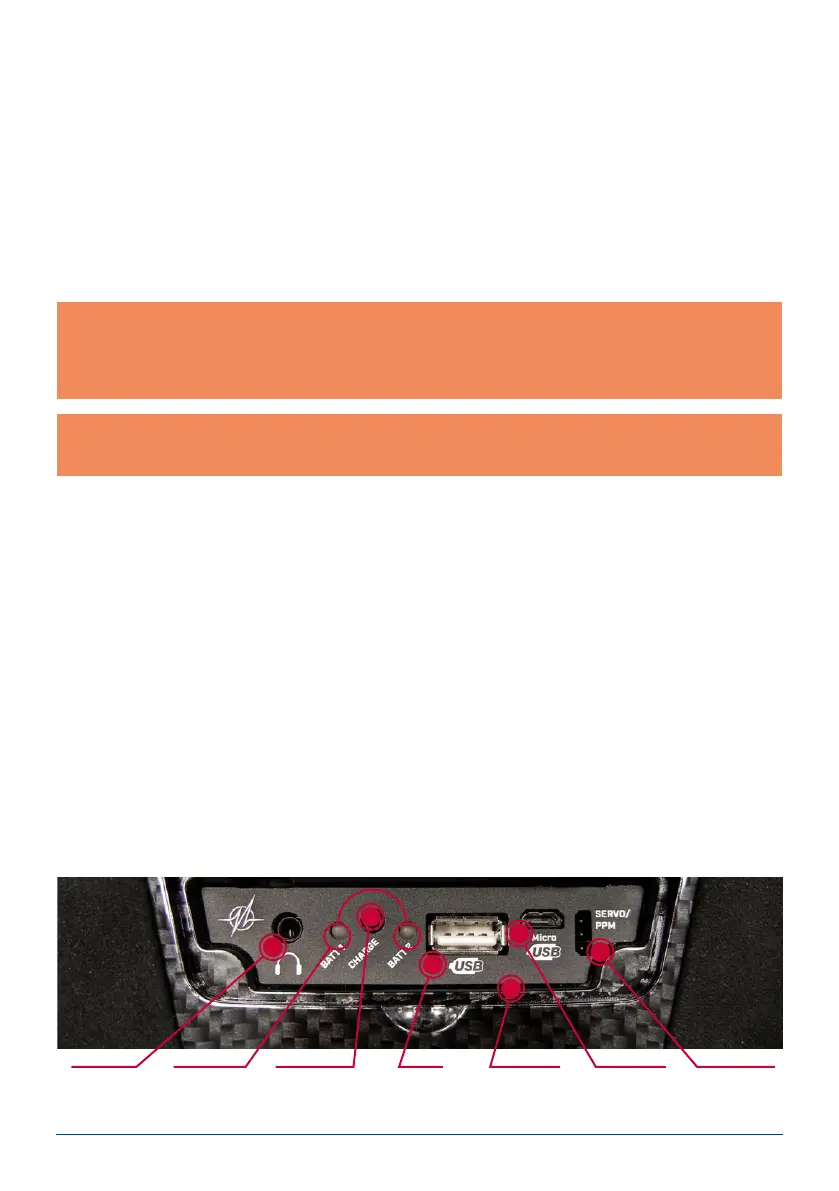
Under the front cover you will nd additional sockets (see illustration on page 4):
- Headphone socket: stereo headphones can be plugged in here for spoken vario or telemetry messages.
- USB-A socket: this accepts a USB stick, which can be used to update the radio control system. Data from the
CORE can also be copied onto the USB stick.
- Micro USB socket: for direct exchange of data with a PC.
- Servo / PPM: servos plugged into this socket respond directly to the movements of the primary sticks. This
can be extremely useful for centring servos accurately before installation, or for subjecting them to a brief
function test. This output is protected with a 1A fuse, and is therefore not suitable for load-testing servos!
It is also possible to switch this socket to P²-BUS output in order to supply external varios or recording devices
with real-time telemetry from the model. In a future update, this connection will also work as an S.BUS input to
provide a teacher / student function.
Note: in addition to the bar display at top left on the screen, you can also set up the transmitter to display
its own exact battery voltage on the main screen in the form of a telemetry widget, and set a corresponding
alarm. The transmitter is tted with two internal 7.2 V Li-Ion batteries of 3400 mAh capacity. Sensible alarm
values would be 6.8 V for an orange alarm, and 6.6 V for a red alarm.
Note: the mains PSU is the same type used for PowerBox Batteries and PowerPaks, and can also be used
to recharge these batteries.
15. CHARGING THE TRANSMITTER
If you wish to charge the CORE, the rst step is to open the front cover. Locate the two plugs attached to the
mains PSU, and insert either one into the charge socket. If the battery symbol is displayed large and ashing on
the screen, this means that you have a reserve for about 20 – 30 minutes. You must charge your CORE at this
point, if not sooner. For safety reasons the CORE does not feature a battery cut-off. Never allow the transmitter
to become deep-discharged!
The LEDs light up red when the batteries are on charge, and green when the charge process is complete. The
charger can be left connected to the CORE after charging without causing damage, as the internal charge control
circuits regulate the charge process completely automatically. The battery charge process takes about 3.5 hours
from the fully discharged state.
The CORE can also be recharged while it is switched on, e.g. for protracted programming work.
Headphone
socket
Charge status
LED
Charge socket
(10-16V)
USB-A
socket
Microphone
input
Micro USB
socket
Servo tester/
PPM output