www.powerbox-systems.com
9
3. FUNCTION MENU
You now arrive at the most important screen display:
the Function Overview. In principle, the set-up of the
whole model is carried out from this starting point.
The display is arranged logically from left to right:
Function Transmitter control Trim Setup
Failsafe Servo(s)
The individual points in detail:
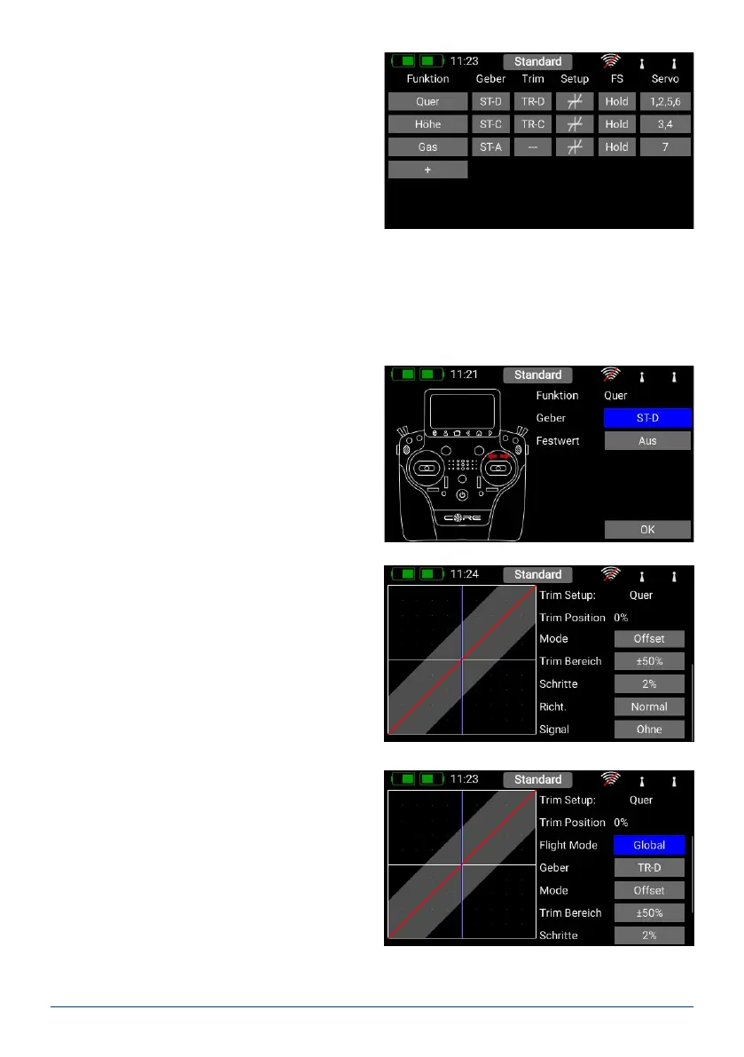
A. Function
Each function always contains a transmitter control, the associated trim, the settings for the transmitter control
– such as Expo and Travel, Failsafe or Hold – and the assigned servos.
Each function can also be renamed just as you wish at this screen: simply touch the Function name.
B. Transmitter control
At this point you can assign a transmitter control or a
xed value to the function. A transmitter control may
be a primary stick, a proportional control, a switch or
a push-button:
C. Trim
a) Flight mode
Here you can select whether the effect of any trim
adjustment is to be Global – i.e. the trim value
should be the same in all ight modes – or Single
– i.e. the trim value should be variable separately in
each ight mode. The method of using ight mo-
des is discussed later.
b) Trim control
It is necessary to assign a trim control as the rst
step here. This can be one of the four trims loca-
ted adjacent to the primary sticks, or two of the
four rubberised push-buttons. If you select the
push-buttons, the buttons always work together
left and right as the trim.
c) Trim mode
You can choose any of four different trim modes.
The standard one is Offset mode: In this mode a
trim adjustment affects the entire range of stick
travel, i.e. including the end-points. Alternative trim
modes are Left and Right; typically these are inten-
ded for idle adjustment in the case of engines and
turbines. In the Center trim mode any adjustment
only affects the center range, i.e. the end-points re-
main unchanged.