10 PowerBox-Systems − World Leaders in RC Power Supply Systems
d) Trim range
At this point you can limit the permissible trim range. The percentage value indicates the maximum trim travel
in each direction.
e) Steps
Here you can set the number of trim steps or increments; not the size of the step.
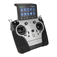
a) Flight mode (ight phase)
If you want the adjustments you make to affect all ight modes, set this menu point to Global. If you set this
point to Single, you can carry out individual adjustments for each ight mode separately. This tool is extremely
powerful, but if you wish to make use of it you must rst create ight modes – more on this later.
Once you have set up the ight modes, all you need to do is activate them, then enter your preferred adjust-
ments for the transmitter control concerned. The transmitter control settings (travel, curve, etc.) which you
enter for, say, the “Landing” ight mode, will then have no effect in the “Thermal” ight mode.
b) Transmitter control rate
Here you can select a transmitter control which switches the rate on and off, or sets it to linear. The transmitter
control can be any of the primary sticks, proportional controls or switches.
c) Rate
The purpose of the Rate button is to adjust the travel of the transmitter control. If you select nothing for Trans-
mitter control rate, the value is xed. If you assign a transmitter control to Transmitter control rate, you can
set different values on three levels. The level initially selected with the transmitter control you have selected
is shown in green. If you select a proportional control as transmitter control, the values are applied in a linear
fashion within the three levels.
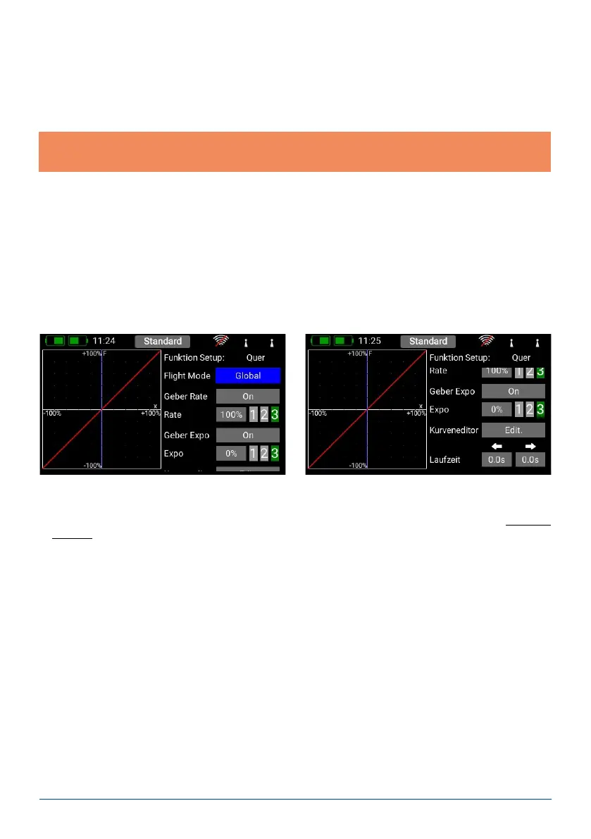
d) Transmitter control expo
At this point you can select a transmitter control which is used to switch an Expo characteristic, or set it to
linear. You can choose any transmitter control from the primary sticks, proportional controls or switches.
D. Setup
At this point you can adjust the transmitter control input, Expo, transit time and curves.
Note: if you change the Min. / Max. values but leave the number of steps the same, the step size changes
accordingly.
f) Direction
Here you can set the direction of the trim control; for example, you may need this function in connection with
the trim buttons.
g) Signal
At this point you can set whether the trims are to generate an audio signal when they are adjusted, or when
they pass through the center point. A vibration signal is also available.