15
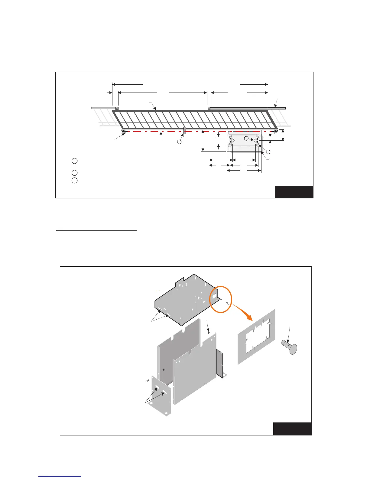
INSTALLATION OF CEMENT PAD
INSTALLATION TO PAD
Lay out the cement pad as shown in Figure 2. Be sure top surface is level. Allow 2 days cure
time before installing operator. Bolt pattern must be parallel to the gate.
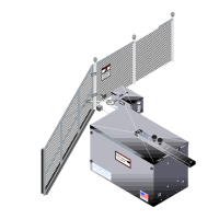
1. Assemble stand and mount power head using carriage bolts. See Figure 3.
C
L
.
3” O.D. Pipe, extending min. 18” above ground
only required for optional post mounting (2) places
1/2” mounting hardware (4) places (not supplied)
Install Chain Support Bracket as required
1
2
3
Min. Gate Lenth = Gate Opening + A + B + 40”
2
1
3
Gate
Opening
Gate
Gate
Bracket
AB
Fence
10-1/2”
16-5/8”
3-3/4”
14”
7-1/2”
11-3/4”
9”
30”
22”
14” X 30”
Cement Pad
of Drive Chain
40” min.
Base of
SG Power Head
These slots are for use with
optional pipe mount Installation
(typical both ends)
These slots are for use with
optional pipe mount installation
(typical both ends)
Carriage
Bolt
Nut
SG Stand
Assembly
FIGURE 2
FIGURE 3