24
LOOP DETECTOR SYSTEMS AND INSTALLATION
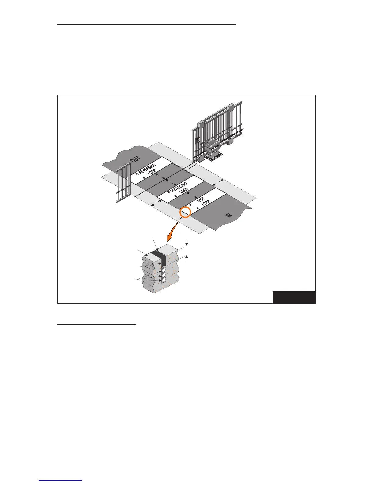
Figure 8 below depicts the typical loop options for a Slide Gate installation.
1. The Exit Loop provides a signal to open the gate when a vehicle enters the loop zone.
2. The Reversing Loop protects a vehicle in the loop zone from being contacted with
the gate by overriding any close signal while the gate is open, and by reversing the gate
if closing.
LOOP INSTALLATION
1. Lay out the desired loop locations per the diagram. The standard size chart on the
following page will give an approximate length of wire required for various loop
dimensions and number of turns required.
NOTE: Length of lead-in wires must be added to loop lengths for total length of wire
required.
CAUTION: The loop wires and lead-in wires must be a continuous piece of wire
without splices. Only use wire intended for this type of application (Type XHHW
insulation 16AWG).
NOTE: Buried steel from drains or other systems may aect functioning of the loop
system. Check with the factory for advice on any special installations. Call 1-800-243-4476.
4'
4'
4'
4'
4'
4'
4'
4'
Loop wires
Min 1”
Road Surface
Sealant
3/16” to 1/4”
Saw Slot
FIGURE 7