26
3. Leaving enough wire for the lead-in, insert the specied number of turns of wire in the
cut grooves (See chart).
CAUTION: Be careful not to damage the wire insulation during installation.
4. After completing the required number of loop turns, twist the ends together at the rate of
6 turns per foot to form the lead-in.
5. Seal the lead-in wire in the conduit to prevent moisture seepage into the conduit.
6. Fill over the loop wires in the groove with a recommended loop sealant. Contact your
distributor for available sealants.
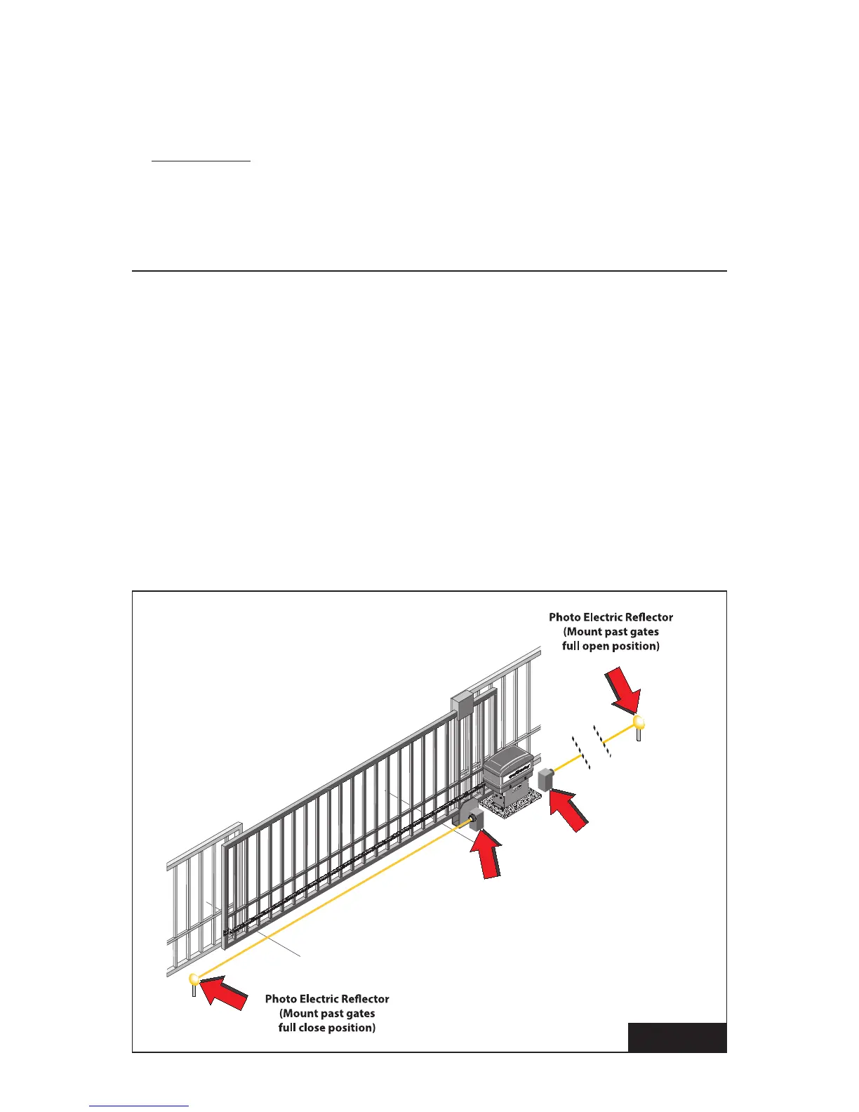
SAFETY DEVICE CONNECTIONS
NON-CONTACT SENSOR INSTALLATION
1. Install photoelectric cell as close to inside of gate as possible. Photocells should be
installed across the gate opening and behind the gate, at least 10 inches above ground
(see Figure 10).
NOTE: A separate pedestrian gate must be installed if there is no other entry access but
the vehicular gate.
Photo Electric Cell
(For open direction)
Photo Electric Cell
(For close direction)
FIGURE 10