20
CONNECTION OF INCOMING POWER
NOTE: Wiring to operator must use watertight materials in accordance with local electric
code. See wire gauge/distance charts for proper sizing. Master/Slave installations should
have SEPARATE power supply wiring or length of wire runs should be gured at half that
shown on the chart. This unit must be grounded in accordance with N.E.C. and local codes.
NOTE: Before connecting the operator, use a voltmeter to determine that the electrical
service is 115V. THIS OPERATOR CANNOT BE CONNECTED AT 230 VOLTS. Damage will result
which is not covered under warranty.
ELECTRICAL SET-UP AND CONNECTIONS
DO NOT APPLY POWER UNTIL TOLD TO DO SO! RISK OF
ELECTRICAL SHOCK OR INJURY MAY RESULT!
WARNING
NOTE: Before connecting the operator to an incoming power supply, use a voltmeter
to determine that the electrical service is the same as that on the operator label. If the
operator is connected to an incorrect power supply, damage will result, which is NOT
covered by warranty.
1. Be sure both the power switches at the source and at the operator are OFF.
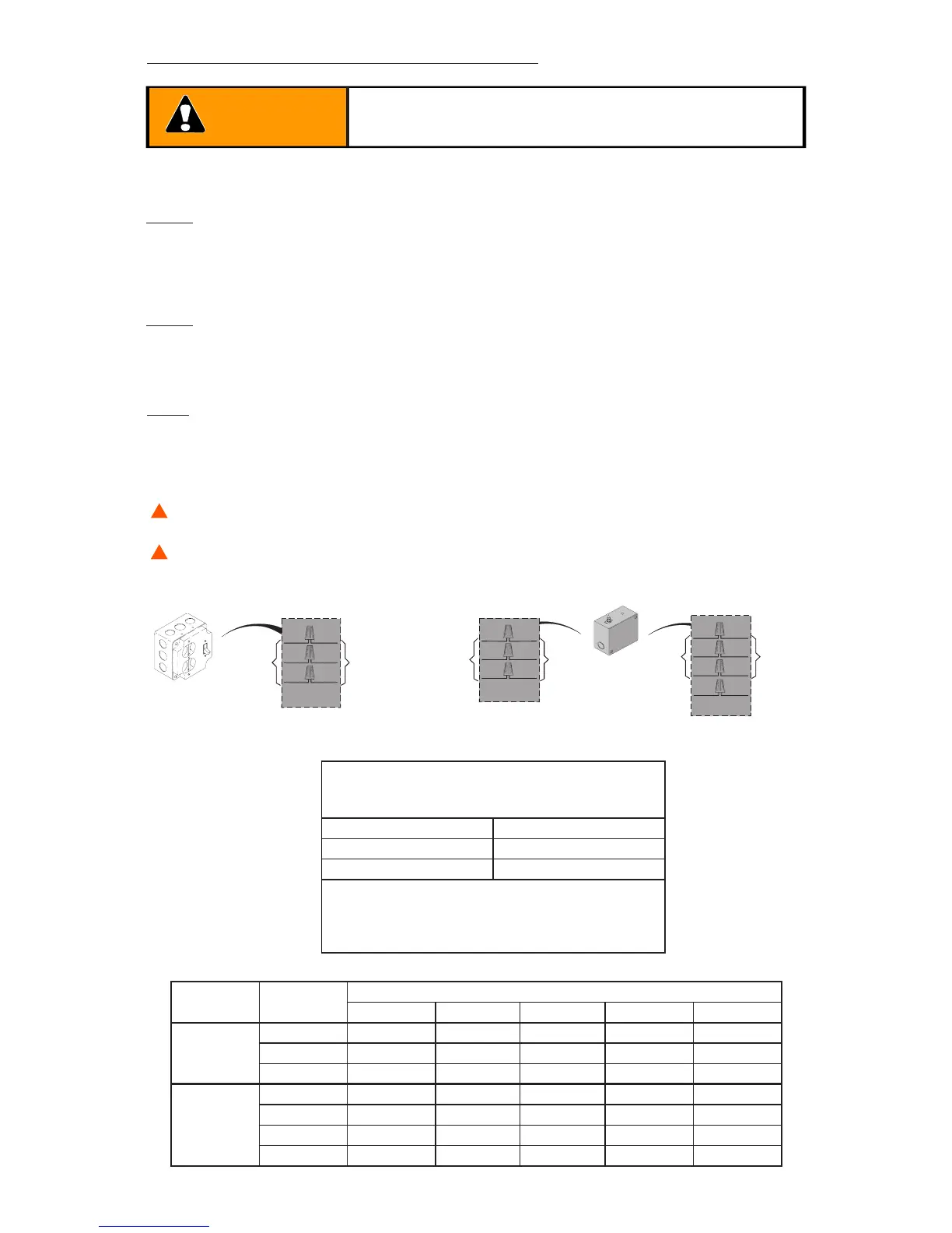
2. In the diagram below, nd the supply power that matches your installation and
connect as shown.
Line
Voltage
HP
WIRE GAUGE
14 AWG 12 AWG 10 AWG 8 AWG 6 AWG
1 PH
115/
208-230
1/2 150/350 250/400 400/500 500/700 650/1000
3/4 150/250 250/400 400/600 500/850
1 150/300 250/450 400/700
3 PH
208-230/
440-480
1/2 450/2000 750/3000 1200/4300
3/4 350/1500 600/2400 900/3700 1100/4500
1 300/1200 450/1900 750/3000 900/4800
1-1/2 200/800 400/1500 500/2000 900/4800
LOW VOLTAGE
WIRE GAUGE/ DISTANCE CHART
24 AWG: Up to 150’
20 AWG: 150’ - 200’
18 AWG: 250’ - 1,500’
Control wiring should be run as twisted pairs.
DO NOT run control wires in the same conduit
as power wires, telephone wires, or loop
detector leads.
INSI DE UTILITY BOX,
CONNEC T AS SHO WN
INSI DE UTILI TY BOX ,
CO NNEC T AS SHO WN
INSIDE UTILITY BOX,
CONNECT AS SHOWN
INCOMING
POWER
INCOMING
POWER
INCOMING
POWER
OPERATOR
OPERATOR
OPERATOR
UTILITY BOX
UTILITY BOX
ALL - 30
220V - 10
115V - 10
BLKBLK
BLK
WHT
BLKBLK
BLK
GND
GND
GRN
GND
GND
GRN
BLKBLK
BLK
WHT
BLKBLK
BLK