11
Step 3: Using the supplied RJ11 cable connect the extension port of the current EBM to the
extension port of the next EBM. You will need to connect the EBMs from P1 to P2, or P2 to
P1 respectively.
Install the terminator cable in the RJ11 socket of either the first EBM
Step 4: Turn all breaker switches on the connected external battery modules to “ON" position.
Step 5: Press manual ON/OFF button for 5 secs on each external battery module and all external
battery modules will start up and front panel LEDs will illuminate.
NOTE 1: When first energising EBMs they may be at different states of charge. The BMS requires all
EBMS to be fully charged (or at the same state of charge) for successful operation of the
UPS. Please allow sufficient time for the EBMs to fully charge.
NOTE 2: Based on the UPS charging rating, the maximum external battery module for extension
is 6pcs.
2 INSTALLATION AND SETUP continued
2 INSTALLATION AND SETUP continued
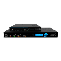
2.7 Setup the UPS
Step 1: UPS input connection
Using the power cord supplied plug the UPS into a two-pole, three-wire, grounded GPO.
Avoid using extension cords.
Step 2: UPS output connection
Please connect devices to the outlets, and pay attention not to overload the UPS.
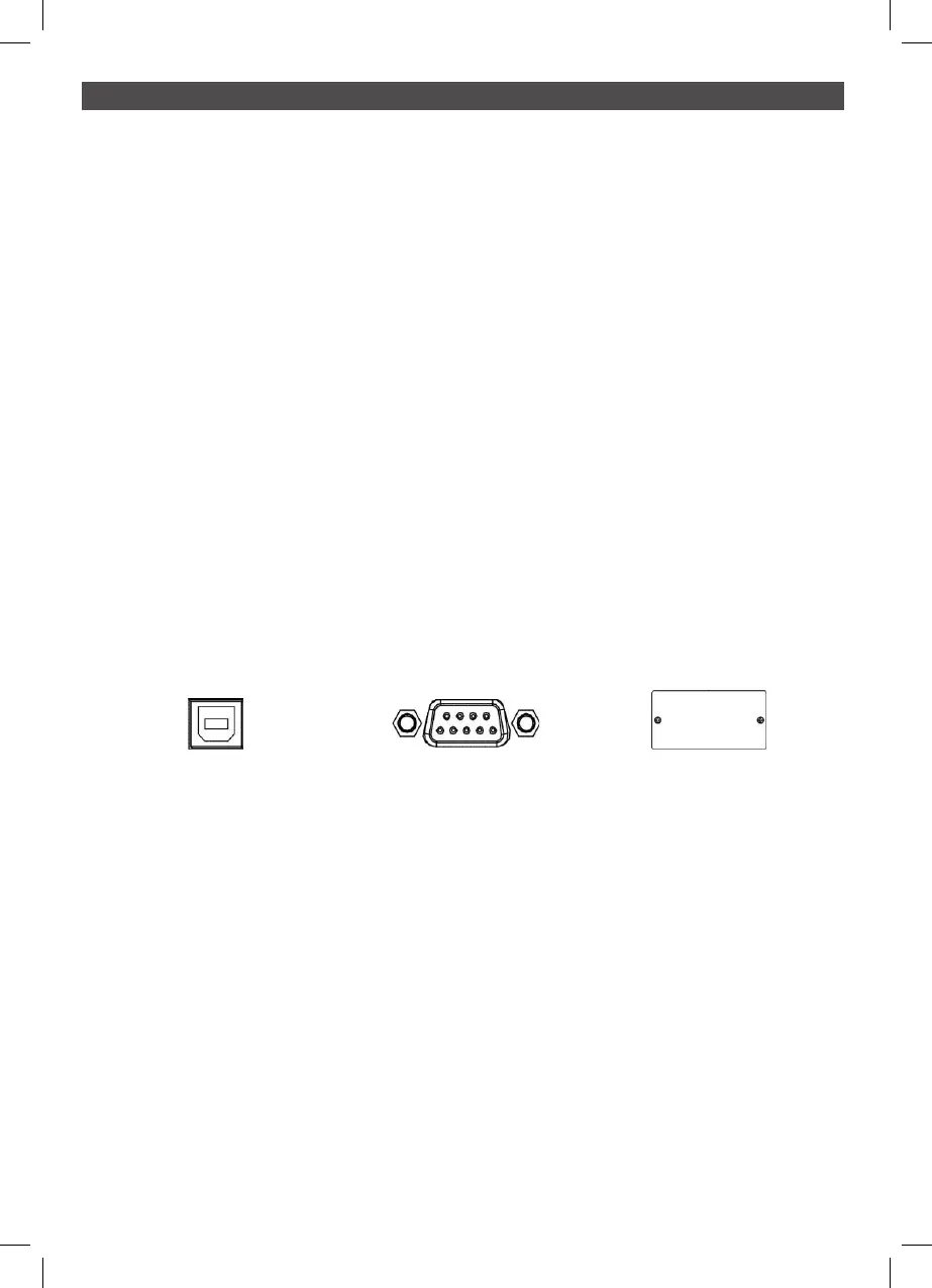
Step 3: Communication connection
To allow for unattended UPS shutdown/start-up and status monitoring, connect the
communication cable with either the USB or RS-232 port and your PC. With the monitoring
software installed, you can schedule UPS shutdown/start-up and monitor UPS status.
The UPS is equipped with an intelligent slot to support either a SNMP or AS400 card for
advanced communication and monitoring options.
USB Port RS-232 Port Intelligent Slot