Powertronix spa reserves the right to modify this document without notice
Page 12 of 46
R&D – USER MANUAL DT0430-E04
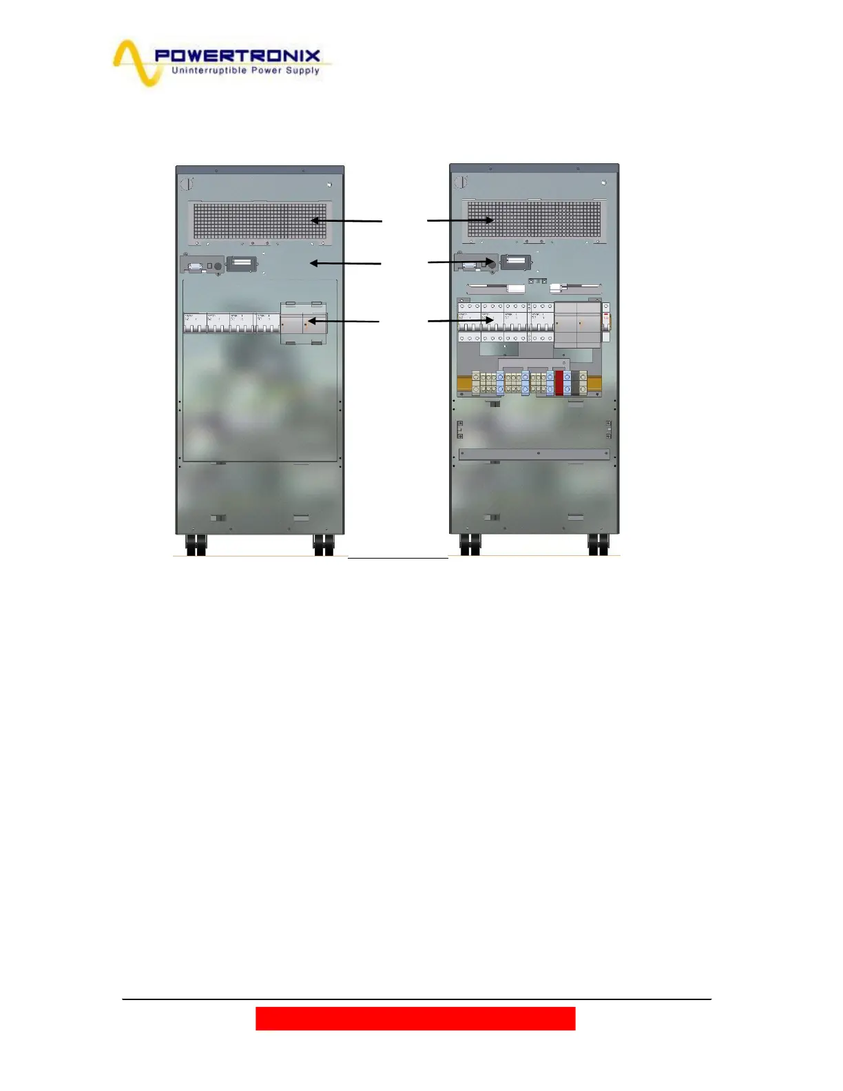
Fig. 2.4 shows the cover and the external connections.
Fig. 2.4
1. Air cooling grid
2. Communication cards slot (Relay & SNMP)
3. Switches
4. Metal cover
Looking at the back, the cables input is located in the lower side, that it is accessible removing the metal cover
(Fig.2.4)
For the cables connection according to the UPS configuration refer to fig.2.6c/d/e at pages 17-18.
3
1
2
Metal
cover
 Loading...