Powertronix spa reserves the right to modify this document without notice
Page 23 of 46
R&D – USER MANUAL DT0430-E04
2.7.3. UPS MANAGEMENT SOFTWARE
This software is used to monitor the conditions of the UPS whit PC connected to the system by the
supplied cable.
For more information on the installation and use of the software see the user manual which came with it.
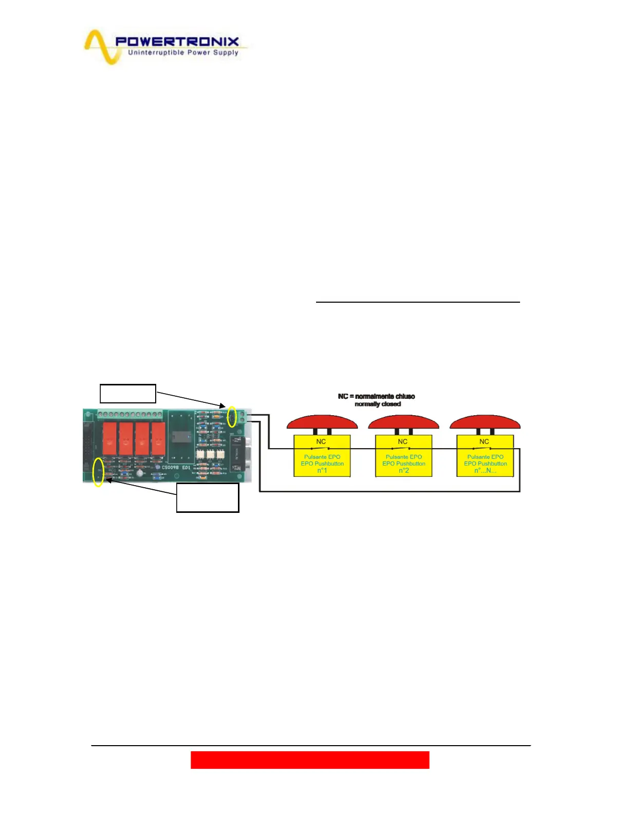
2.7.4. REMOTE E.P.O. BUTTON
Particular attention must be paid to the external connection of buttons or actuators for the EPO function
(emergency stop). This connection is composed of a series of normally-closed switches (Fig.2.7.4) which
open the series if commanded, generating the stop of the UPS with the consequent and irreversible
interruption of voltage to the load. The series of external EPO buttons must be connected to the CN1
terminal board of the relay board CS0098*.
The remote communication card must be configured as described in fig. 2.7.4
If there are no external EPO contacts to the system jumper JP1 must be closed. (circle in fig.2.7.4)
The default configuration (with any ext. E.P.O connected) has the connector CN1 shortened with a wire
connection, it must be removed (as well as the jumper JP1), when one or more E.P.O. ext. is connected
to the board
*If is required to enable the EPO remote on the optional communication card is necessary contact the service.
Fig. 2.7.4
JP1: Open
JP2: Open
JP3: Closed
 Loading...