Powertronix spa reserves the right to modify this document without notice
Page 14 of 46
R&D – USER MANUAL DT0430-E04
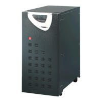
2.6 LAYOUT AND CONNECTION TO THE MAINS
For connection to the mains a layout solution like the one shown in diagram 2.6 is recommended. The
circuit breakers B-C-D are magnetothermic type without differential protection, or if this is required, with a
triggering current greater than 0.3A, delayed and suitable for load with DC current (type A).
Switch A is used as external BY-PASS.
Block diagram 2.6
Config.: 3 in – 3 out
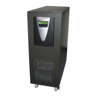
Config.: 1 in – 1 out
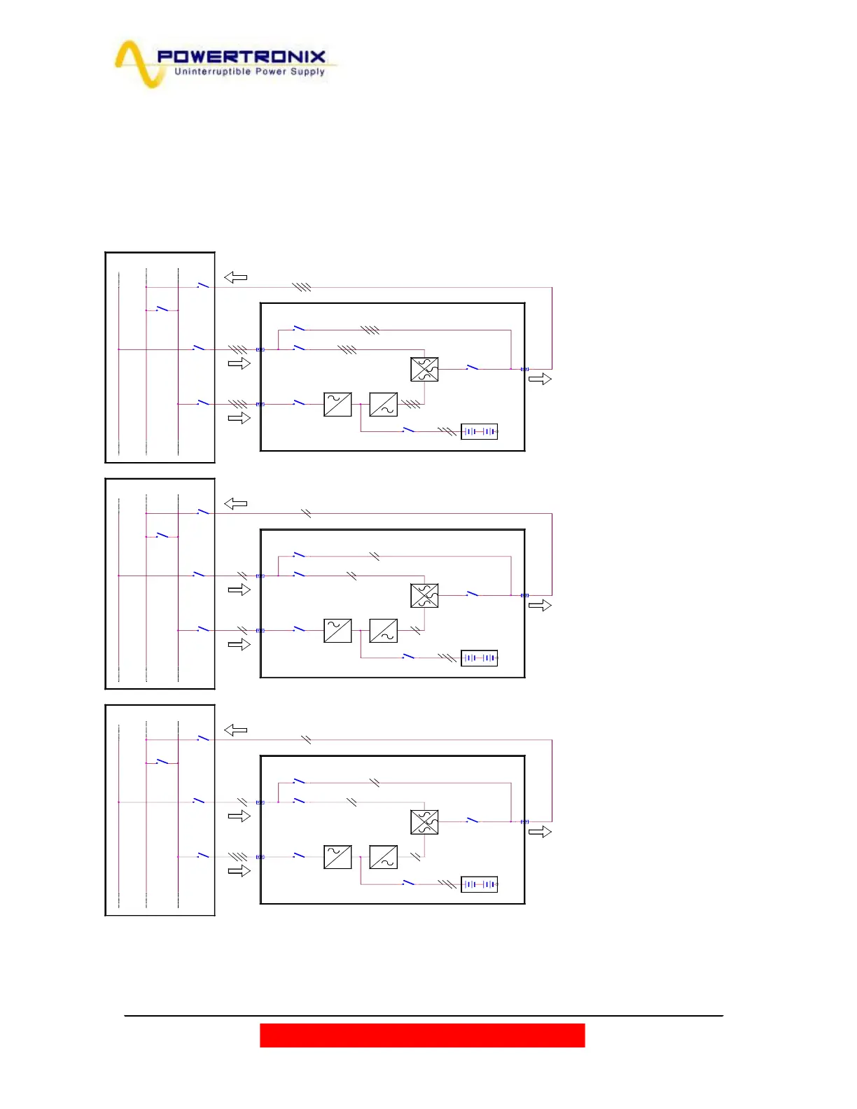
Config.: 3 in – 1 out
BATTERIE INTERNE
I5 BATTERIA
I2 INPUT RISERVA
I3 BY-PASS
I4 USCITA
I5 BATTERIA
I4 USCITA
BATTERIE INTERNE
I1 INPUT MAINS
I2 INPUT RISERVA
I3 BY-PASS
BATTERIE INTERNE
I3 BY-PASS
I2 INPUT RISERVA
I1 INPUT MAINS
I5 BATTERIA
I4 USCITA
I1 INPUT MAINS
=
=
RESERVE LINE
CARICO
RE TE PRINCIPA LE
PANNELLO DI
DISTRIBUZIONE
UPS
C
B
D
RETE DI RISERVA
A
=
=
RESERVE LINE
CARICO
RETE PRINCIPA LE
PANNELLO DI
DISTRIBUZIONE
UPS
C
B
D
RETE DI RIS ERVA
A
RESERVE LINE
C
UPS
A
=
PANNELLO DI
DISTRIBUZIONE
=
D
RETE PRINCIPA LE
RETE DI RISERVA
CARICO
B
 Loading...