Installation
5
Powerware
®
5105 User’s Guide S 05146193 A Uncontrolled Copy
UPS
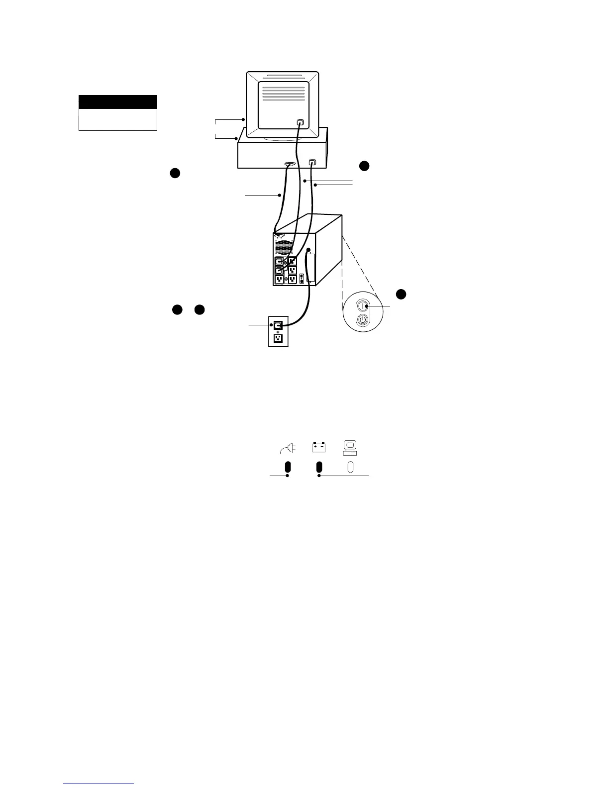
This is a typical setup;
your setup m ay vary.
NOTE
Load
1
Connect communication
cable from computer to
UPS (optional)
Connect UPS to power
4
Connect equipment
to UPS
5
Press the ON button
(on the front panel)
2 & 3
Figure 2. Typical UPS Installation (120V Model Shown)
3. Plug the UPS power cord into a power outlet.
The UPS conducts a self-test and enters Standby mode. If a red
Site Wiring Fault or Battery Service indicator stays on, see
Table10onpage31.
Site Wiring Fault
Indicator
Battery Service
Indicator
Figure 3. Fault Indicators