23
Powerware
®
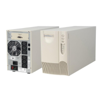
5105 User’s Guide S 05146193 A Uncontrolled Copy
CHAPTER 6
ADDITIONAL UPS FEATURES
This section describes:
S UPS communication capabilities
S The Network Transient Protector
S Load segments
S Option modules
Communication Port Configurations
To establish communication between the UPS and a computer, connect
your computer to the UPS communication port using the supplied
communication cable.
CAUTION
To prevent damage to your equipment, connect only a factory-supplied cable or a cable
built to factory specifications (see Table 2) to the communication port. A standard
serial cable may damage your computer.
When the communication cable is installed, power management
software can exchange data with the UPS. The software polls the UPS for
detailed information on the status of the power environment. If a power
emergency occurs, the software initiates the saving of all data and an
orderly shutdown of the equipment.
Communication Indicator
When the UPS receives a command fr om the computer to establish
communication, the Communication indicator on the UPS front panel
illuminates (see Figure 8 on page 10). When data is transferring, the
Communication indicator flashes.
Pin Out
As shown in Table 2, Pins 1 and 2 operate in two modes: Basic Alarms
mode and Serial Data mode. Basic Alarms mode has AC fail alarm and
output shutdown. Serial Data mode is UPS Code II compliant.