page no. 29 of 40
VPx Range Users, Installation & Servicing Instructions Doc Ref M205 issue 1.2 Nov 2018.
2. Disconnect the spark and rectification leads from the
control box and remove the electrical plug connections
from the top of the gas control valve assembly.
3. Remove the burner heat shield, 3 screws.
4. Release the inlet connection flange from the gas valve
by removing the four screws.
5. If required remove the manifold by removing the four
screws securing it to the burner assembly.
6. Remove the two screws that secure the top of the
burner assembly to the bulkhead and lift out burner
assembly.
7. Using a stiff brush, not a wire brush, brush the
burners to dislodge accumulated deposits. Inspect the
burners both internally and externally to ensure that
they are clean. Examine the injectors and if damaged or
deteriorated, replace with new ones of the correct size
and marking. If deemed necessary, clean the injectors. Do
not broach out with wire.
8. Reassemble the injectors, manifold and burners in
reverse order to that above.
2.7.3. Ignition and Rectification
Electrodes
Note: The ignition electrode is located at the
bottom of the burner assembly, the
rectification electrode is located at the top of
the burner assembly.
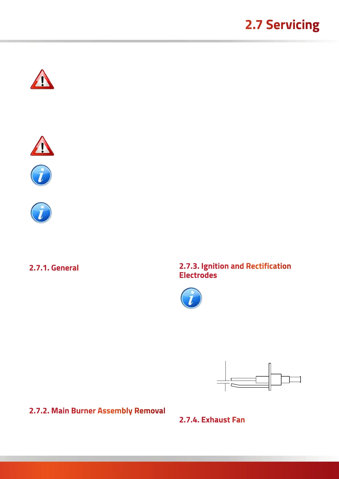
Inspect the electrodes, making sure that they are in a
sound and clean condition. In particular check that the
ignition electrode is clean and undamaged. Check that the
spark gap is 2.5mm and that the rectification probe is 10 -
12mm forward of the burner.
2.5mm
Ignition Electrode Spark Gap
2.7.4. Exhaust Fan
1. Remove the four screws securing the flue outlet socket.
Gas Safety (Installation & Use) (Amendment)
Regulations
It is law that all gas appliances are installed,
adjusted and, if necessary, converted by
qualified persons* in accordance with the
current issue of the above regulations.
Failure to install appliances correctly can lead to
prosecution. It is in your own interests and that of safety
to ensure that the law is complied with.
* Gas Safe Registered Engineer
WARNING: Always switch off and disconnect
electricity supply and close the gas service
valve before carrying out any servicing work
or replacement of failed components.
NOTE: If a suspended air heater is to be
serviced do not lean ladders against the
heater.
Ensure that an access tower or equivalent is
used.
NOTE: The access door to the controls section
may be removed to improve access.
Open the door to 90°, remove the earth cable
at the bottom, and then lift the door vertically
upwards to disengage the hinge plates.
Refit in reverse order. Ensure that the earth
cable is refitted.
2.7.1. General
Full maintenance should be undertaken not less than once
per year by a qualified person.
No 'specialised 'tools will be required to carry out this
service.
A fault finding guide is given in section 3.1 to aid servicing.
After any servicing work has been complete, or any
component replaced, the air heater(s) must be fully
commissioned and tested for soundness as described in
Section 2.6.
To commence servicing, firstly open the side access door
by rotating the quarter turn screw(s).
2.7.2. Main Burner Assembly Removal
1. Ensure that the gas service valve is turned OFF
and then unscrew the union nut situated immediately
downstream of it.
2.7 Servicing

 Loading...