page no. 31 of 40
VPx Range Users, Installation & Servicing Instructions Doc Ref M205 issue 1.2 Nov 2018.
2. Remove the electrical connections from the limit
thermostat.
3. Remove the securing nut and remove thermostat from
the front panel.
4. Fit replacement thermostat in reverse order.
Note*: VPx35 & 90 - 140 units have a second
limit stat at the opposing end of the heater to
the burner/controls. Remove the two small
cover plates and replace as above.
2.7.6.5. Exhaust Fan
1. Remove the four screws securing the flue outlet socket.
2. Disconnect the fan electrical connections from the main
terminal strip
3. Remove the screws securing the fan mounting box to
the exhaust header plate.
4. Remove fan assembly.
5. If needed, transfer the fan mounting box to the
replacement fan.
6. Fit replacement exhaust fan, using new gaskets and
silicon sealant as necessary, and reassemble in reverse
order.
2.7.6.6. Air Pressure Switch
1. Remove the two screws securing the cover and remove
cover.
2. Disconnect electrical connections.
3. Pull off the sensing tube from the air pressure switch.
4. Remove the screws fixing the air pressure switch and
remove switch.
5. Fit replacement in reverse order refitting the sensing
tube to the negative (- or L) tapping on the pressure
switch.
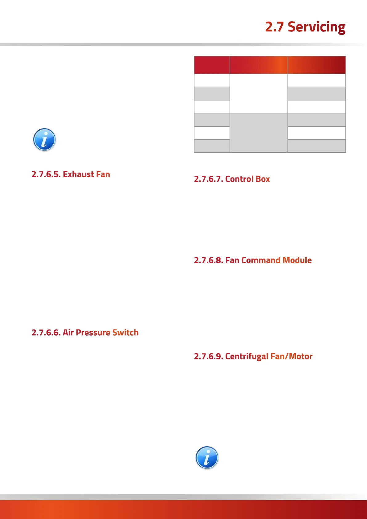
6. Adjust pressure switch set point to that shown in the
following table:
Model
Pressure Switch Setting (Pa)
LNVx35
146522176
180
LNVx50 180
LNVx70 200
LNVx90
146522177
300
LNVx120 350
LNVx140 330
2.7.6.7. Control Box
1. Unplug all the electrical connections.
2. Remove the two screws that secure the control box in
place.
3. Fit replacement in reverse order.
2.7.6.8. Fan Command Module
1. Unplug all the electrical connections by squeezing each
side to release.
2. Using a small flat screwdriver push on the locking tab
of each PCB mount and gently ease the board upwards to
release.
3. Fit replacement in reverse order.
2.7.6.9. Centrifugal Fan/Motor
1. Disconnect the electrical connections to the centrifugal
fan section.
2. Remove the side panels of the section for access to the
fan and motor.
3. Fit replacements as appropriate and reassemble in
reverse order.
Note: If a 3ph motor is being replaced ensure
that the direction of rotation is correct. If it is
not interchange any two of the three phases
connected to the motor.
2.7 Servicing

 Loading...