page no. 19 of 40
VPx Range Users, Installation & Servicing Instructions Doc Ref M205 issue 1.2 Nov 2018.
2.4.1. Electrical Connections
Warning: THIS APPLIANCE MUST BE
EARTHED.
Warning: Lockout reset is by a switched
Neutral to the controls in the heater.
Warning: Wiring external to the unit must be
carried out by an appropriately qualified
person to current IEE regulations for
Electrical Installations and any local regulations which
apply.
The local electrical supply must be run to a point adjacent
to the heater and be suitably terminated to provide an
isolation point that will prevent remote activation of
the unit during servicing. Wiring should be completed in
flexible conduit.
The local electrical supply conditions must be compatible
with the electrical data given on the appliance data plate.
Heaters are for use with 230V, 1N, 50Hz supplies.
The method of connection to the main electricity supply
must:-
- facilitate the complete electrical isolation of the
heater(s) via a suitable fused isolator that will prevent
remote activation of the heater during servicing (see
section 2.4.5 for ratings).
- be in a readily accessible position adjacent to the
heater(s).
- serve only the heater(s).
- have a contact separation of at least 3mm in all poles.
See section 2.5 or the accompanying wiring diagram for
the heater electrical connections.
Reference must be made to Section 2.4.5 to ascertain
the electrical loading of the unit(s) being installed so that
cables of adequate cross-sectional area are used for
the electrical installation. The length of the conductors
between the cord anchorage and the terminals must be
such that the current carrying conductors become taut
before the earth conductor if the cable or cord slips out
of the cord anchorage. All external controls must be of an
approved type.
All units are fully prewired and only require final
connections for the incoming mains supply. Heaters not
supplied with inbuilt time and temperature controls will
also require completion of the external control circuit
(230V) via a room thermostat, time clock etc. and, if
applicable, the remote low level lockout reset see 2.4.5.
Note: To achieve maximum system efficiency it
is recommended that VPx units are controlled
by an MC200 or MC300 unit. Simple room
thermostat and thermostat/time clock control
systems will not provide optimum system efficiency and
fuel savings.
Wiring drawings and instructions are supplied with the
respective controller.
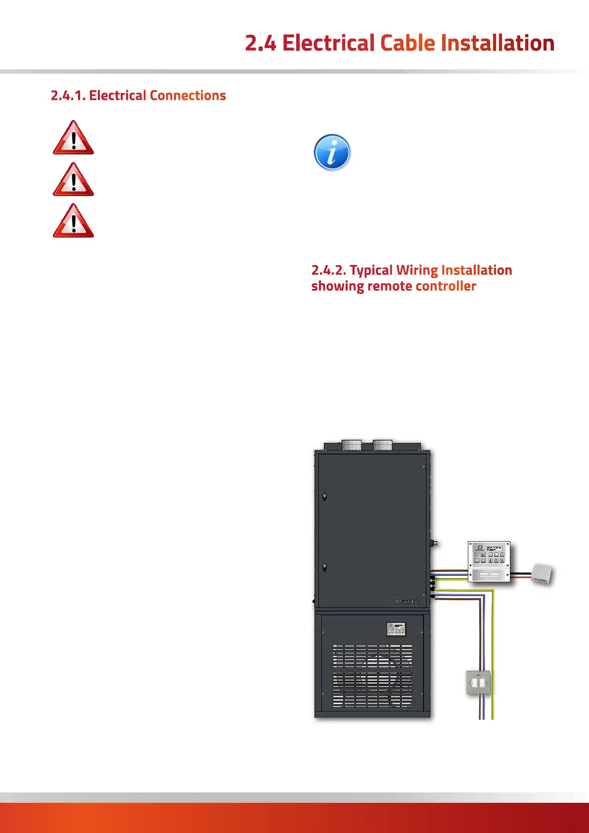
2.4.2. Typical Wiring Installation
showing remote controller
Key:
Mains supply = 2 core and earth
MC200 Controller = 8 core and earth
alt. MC300 Controller = 6 core screened + LNE
Optional MC200 sensor = Screened 2 core*
* (screen must be grounded only at the MC200, See
instructions supplied with controller for wiring sizing,
Max. 100m)
2.4 Electrical Cable Installation
Optional
Remote Controller
(MC200 shown)
Remote
Sensor
(optional)
Typical wiring
installation
Fused
Isolator
230V Supply shown
(415V option on 90-140)

 Loading...