page no. 20 of 40
VPx Range Users, Installation & Servicing Instructions Doc Ref M205 issue 1.2 Nov 2018.
Single Phase Units Three Phase Units
Model
Running
Current (A)
Fuse/MCB Rating (A)
Running
Current (A)
Fuse/MCB Rating (A)
(motor rated Protection Device)
VPx35
4.7 10 / 6 N/A N/A
VPx50
7.6 10 / 10 N/A N/A
VPx70
11.0 15 / 16 5.3 10 / 10
VPx90
9.8 15 / 16 4.2 5 / 6
VPx120
9.8 15 / 16 4.2 5 / 6
VPx140
13.1 15 / 16 8.5 10 / 10
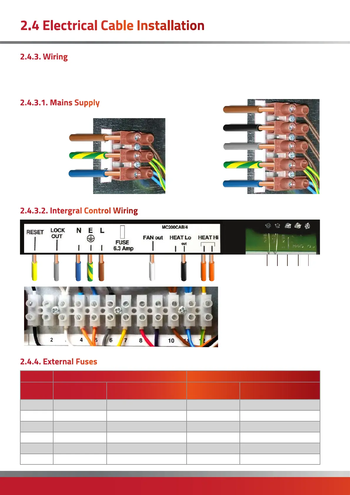
2.4.3. Wiring
2.4.4. External Fuses
2.4 Electrical Cable Installation
The wiring terminals are located on the electrical panel
behind the side door of the heater which firstly has to be
opened.
L
N
E
L3
N
E
L2
L1
Mains input of either 230V 50Hz 1Ph or 415V 50Hz 3Ph
supply connections are via a separate terminal block. For
input power refer to table below.
SEN1
COM
SEN2
V+
0V
3 phase 1 phase
2.4.3.1. Mains Supply
2.4.3.2. Intergral Control Wiring
Integral control
wiring terminal

 Loading...