page no. 21 of 40
VPx Range Users, Installation & Servicing Instructions Doc Ref M205 issue 1.2 Nov 2018.
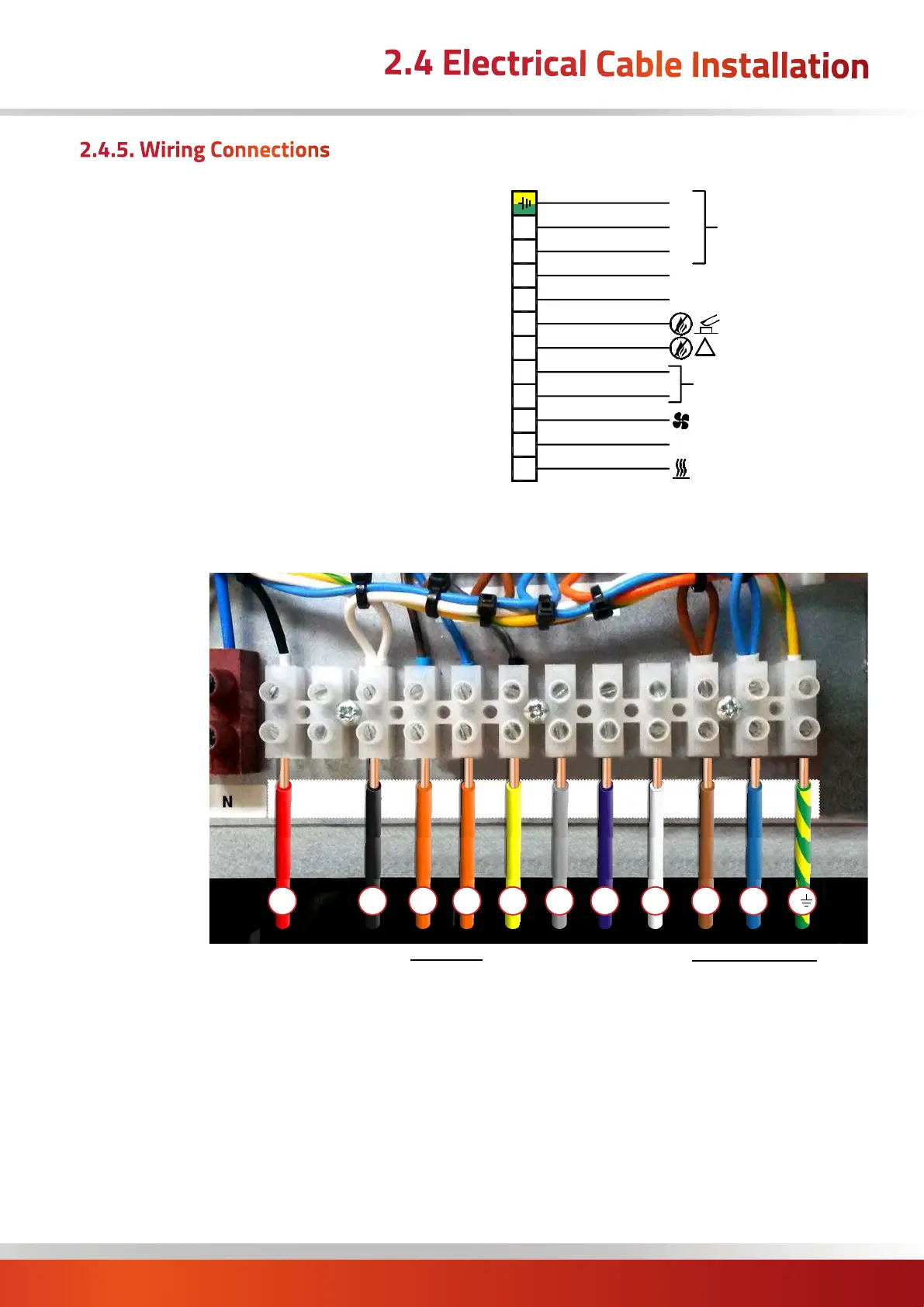
Controlling circuitry is via a numbered terminal strip wired
back to the in-built MC200/CAB controller. If an external
control panel is to be used, then these terminals must be
used. Connection terminals are:
terminal 1 230V Heat Low Demand
terminal 3 230V Main Fan Only
terminal 4 & 5 Heat High Circuit
terminal 6 Lockout indication - 230V Output
terminal 7 Burner reset - Neutral Switch
terminal 8 0-10V d.c. Modulation
terminal 9 0V Modulation
terminal 10 Live to Controller
terminal 11 Neutral to Controller
terminal E Earth to Controller
3
4
5
6
7
8
2
1
1
1
9
1
0
E
N
230v Supply
for Controller
L
Modulating (-)
Modulating (+) 0-10v
Lockout Reset
!
Lockout Indication
- N.O. Thermostat or Relay
- 230v in. ( Delay on, Delay O)
- Accessory Terminal. 4A Fuse Protected
- 230v in. Not used on modulating heaters
High Fire
Call for Fan Only
230v Out
Call for Heat
MAINS SUPPLY
230V AC 50HZ
- Momentary switch to neutral
- 230v out
Heat On Signal 230V
Output 230V
Input 230V
Fan Only Signal 230V
Live Output
Neutral
Earth
230V Supply
for Controller
High Fire
Circuit
Lockout Signal 230V
21 3 4 5 6 7 8 9 10 11 12
t1
t3
t4
t5
t6
t11
t
t10
t7
t8
t9
*Lockout Reset
(Switched Neutral)
*Modulating signal
0-10Vdc
*Modulating signal
0Vdc
Wiring terminal strip for External Controller
* when used
2.4.5. Wiring Connections
2.4 Electrical Cable Installation

 Loading...