23
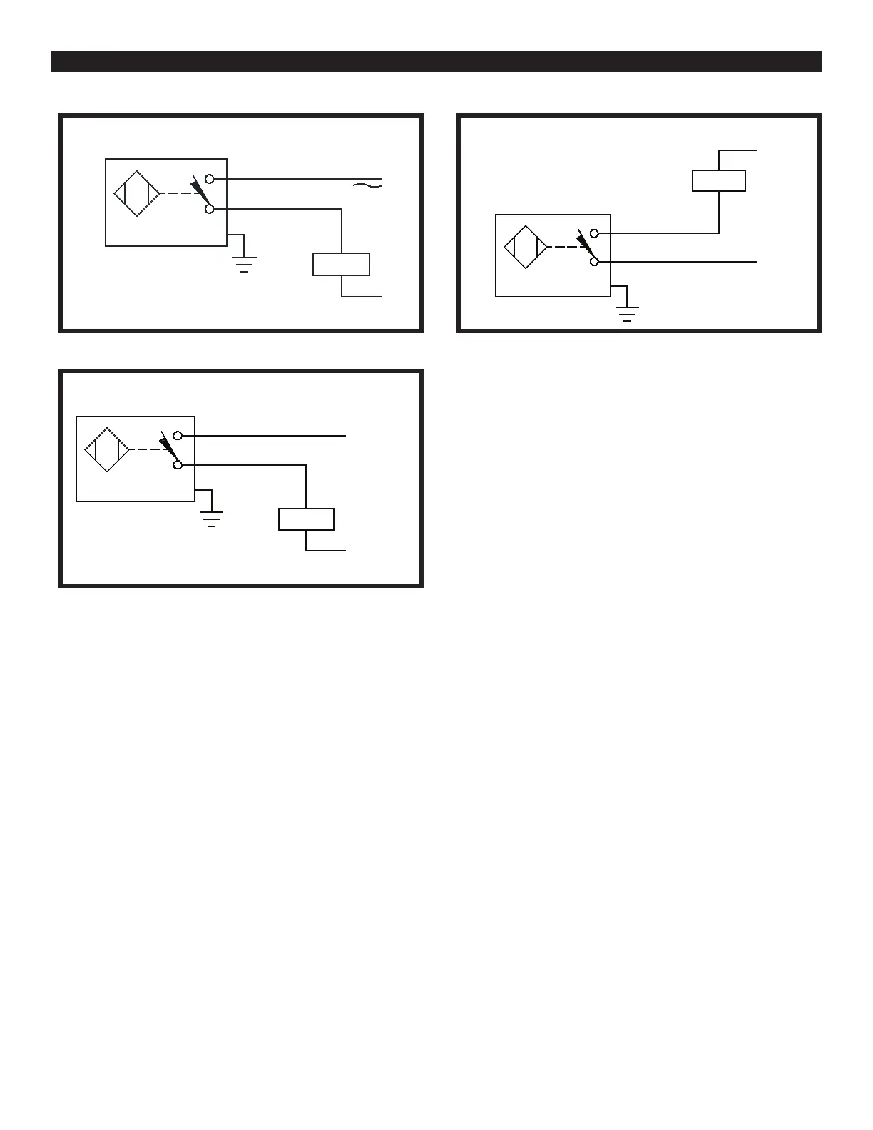
Figures A4.1, A4.2, and A4.3 show Smart Roll Sensor wiring diagrams. For these diagrams, the Smart Monitor or PLC provides the load.
SENSOR SPECIFICATION:
• 2 wire AC/DC inductive sensor
• 20–250 VAC, 10 –300 VDC
• Short Circuit and Overload Protection
• Normally Open
• 2 meter cable, PVC jacket; 22 AWG copper conductors, PVC insulated.
Line Frequency: 50-60 Hz
Differential Travel (Hysteresis): 3-15% (5% typical)
Voltage Drop Across Conducting Sensor: <=6.0V at 100 mA
Continuous Load Current: <= 100 mA
Trigger Current for Overload Protection: >= 220 mA
Off State (Leakage) Current: <= 1.7 mA
Minimum Load Current: >= 3.0 mA
Inrush Current: <=1.0A (<=30ms, 15% Duty Cycle)
Time Delay Before Availability: <=60 ms
Power-On Effect: Per IEC 947-5-2
Transient Protection: Per EN 60947-5-2
Operating Temperature: -25°C to +70°C (-13° F to 158°F)
Repeatability: <=2% of Rated Operating Distance
Temperature Drift: ±10%
A. SMART ROLL SENSOR WIRING DIAGRAMS AND SPECIFICATIONS
BU
BN
LOAD
(YL/GN)
2 Wire DC Sinking (NPN)
Circuit Wiring Diagram
+V
-V
BU
BN
L1
L2
LOAD
(YL/GN)
FIGURE A.: WIRE AC CIRCUIT WIRING DIAGRAM
FIGURE A.: WIRE DC SINKING NPN
CIRCUIT WIRING DIAGRAM
BU
BN
LOAD
(YL/GN)
2 Wire DC Sourcing (PNP)
Circuit Wiring Diagram
+V
-V
FIGURE A.: WIRE DC SOURCING
PNP CIRCUIT WIRING DIAGRAM