4
Please note, care must be taken to avoid scraped, pinched, or crushed
wiring. Wires that are scraped, pinched, or crushed during shipping,
handling or installation will void the warranty.
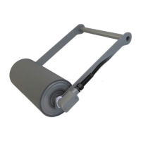
Installing the Clean Side Return (CSR) Smart Roll is shown to the right.
This is the most commonly used Smart Roll. For mounting the Universal,
Trougher or Return Smart Rolls see the appendix.
CLEAN SIDE RETURN MOUNTING INSTRUCTIONS
Setting up the pivot/hinge
Typically, the CSR is mounted on the clean side of the belts return run
using a ¾ inch diameter rod as a pivot or hinge. Figure 2.1 shows a typical
installation for a Clean Side Return Smart Roll on the clean side of the
return run of the belt. Care must be taken to select a location allowing
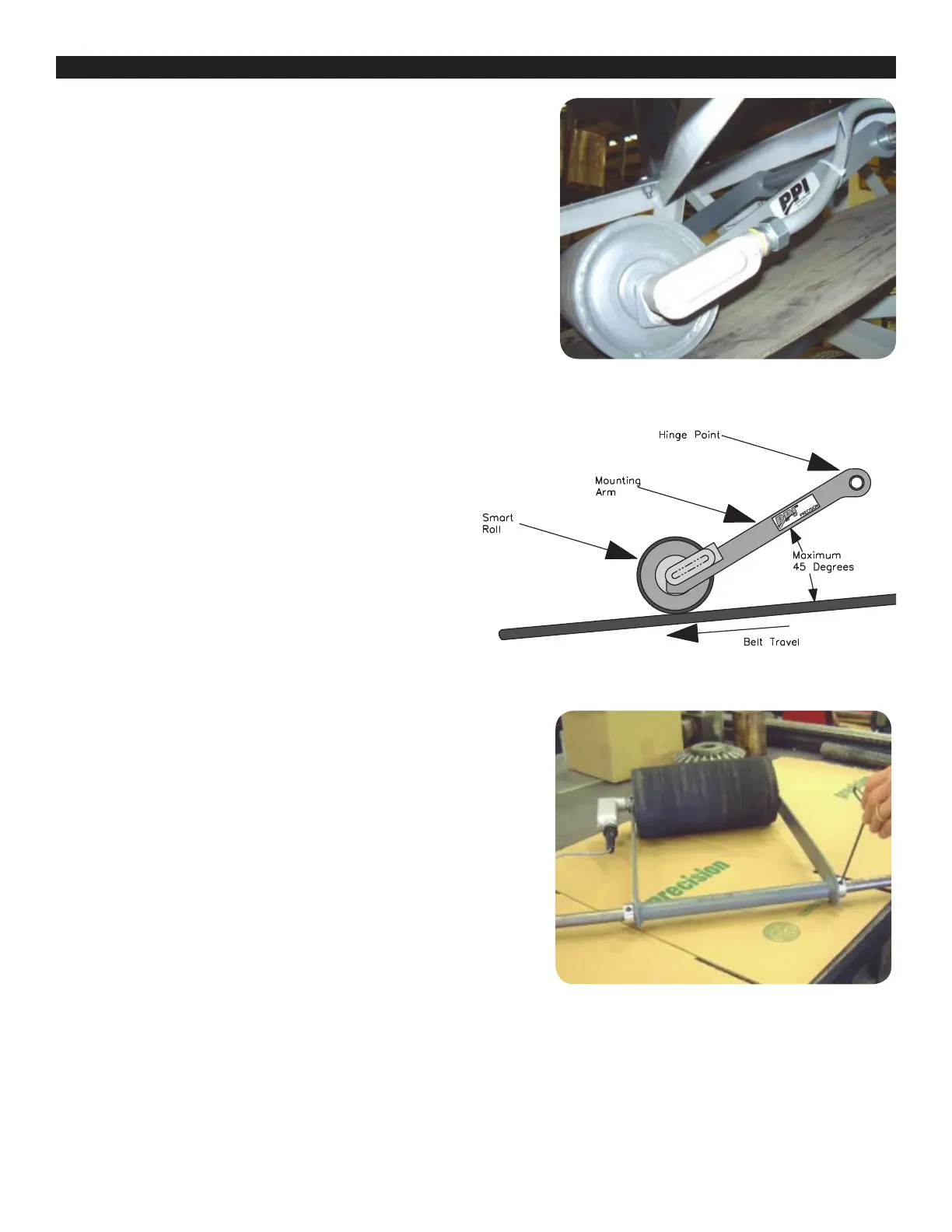
free movement of the CSR hinge, see Figure 2.2. Mounting the CSR in
locations restricting free movement of the roll and/or mounting arm may
cause premature failure and void the warranty. CSR should not be used on
a reversing belt. The angle from the belt to the CSR mounting arm should
not exceed 45 degrees as shown in Figure 2.2. Proper orientation with belt
travel direction, as shown, is critical. Severe roll and/or belt damage
may occur if mounted incorrectly.
Two options are shown for mounting the CSR Smart Roll. Option 1 is
welding the pivot shaft to the conveyor frame work and option 2 is
using mounting brackets bolted to the frame work. Diagrams for the
pivot/hinge options are shown at the end of this section.
Option 1: At the conveyor mounting location, measure the distance
between the conveyor framework where the ¾ inch diameter shaft
will be attached. Cut the shaft to length, removing burrs, and all
sharp edges.
Option 2: At the conveyor mounting location, measure the distance
between the conveyor framework where the holes will be located for
the mounting brackets. This measurement will determine which mounting
bracket hinge option to use.
Options 1 & 2: Insert the ¾ inch diameter shaft through the CSR hinge
point. Center the shaft with the hinge point, and install one retaining collar
on each end of the shaft as shown in Figure 2.3. Turn shaft collars so set
screws are aligned and lightly tighten the set screws.
FIGURE 2.1: Clean Side Return roll in a typical installation. Optional
CSR mounting hardware shown. Conduit and wire tire not included.
FIGURE 2.2: CSR Mounting
FIGURE 2.3: CSR Mounting Accessories test fit in CSR hinge point.
CSR Mounting Accessories sold separately.
INSTALLING AND MOUNTING THE SMART ROLL