28
PART NUMBER SMART MONITOR VAC MA OUTPUT
Description:
Smart Monitor 47269 converts rotary shaft speed (RPM) into analog 4-20mA output. This
allows “true-slip” monitoring during the critical ramp-up period of conveyors. The Smart
Monitor 37545 interfaces directly with the customer’s PLC. The Smart Monitor conveniently
mounts inside an existing electrical panel or O.E.M. control box. The aluminum mounting
plate is removable for mounting to DIN rail. The up-front LCD screen conveniently shows the
current RPM in real time.
Installation:
1. Disconnect AC power before proceeding with installation
2. Mount the Smart Monitor inside and existing control panel or other suitable protective
enclosure. See Figure A5.8 for Smart Monitor mounting dimensions.
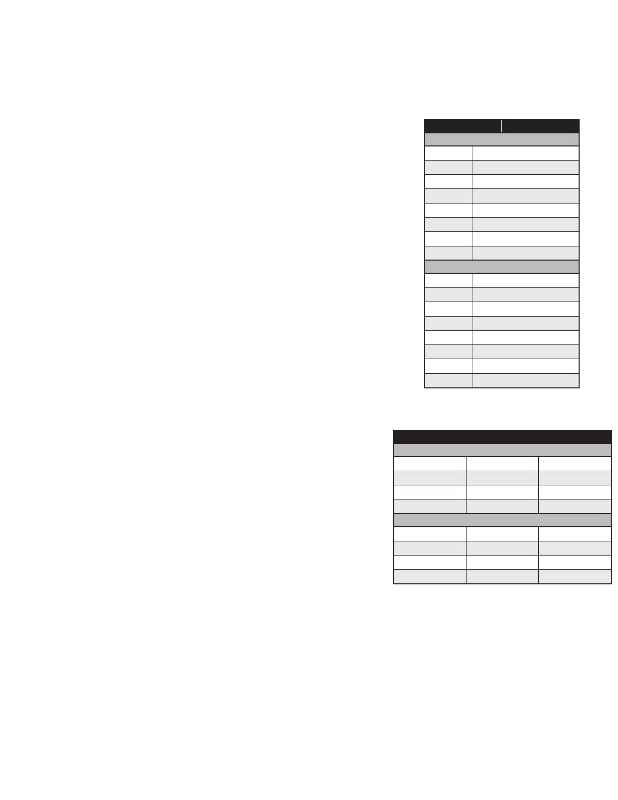
3. Table A5.6 shows connection details for the terminal strip. Make needed connections.
4. Install Smart Roll. See Section 2: “Installing and Mounting the Smart Roll”.
Set-up and Display Indicators:
When power is applied to the unit, the display will show the following: “000” RPM (Displays
the actual RPM from the remote speed sensor).
“Line Open” – If displayed, indicates user should check 4-20mA line. 0-500 ohm is
maximum line resistance.
“10-XXXX RPM” – Displays the current speed range. If this is NOT the correct range required
for your installation, you can select from 23 other preset speed ranges by following the steps
below:
5. Depress and hold the “set” button for approximately 4 seconds. The display will now
change to show ranges from 100 RPM top range to 6000 RPM top range.
6. Now using the “arrow” keys, select the desired range from the list.
7. With the correct range “highlighted,” depress and hold the “set” button for approximately
4 seconds. The display will now change back to normal operation with the new RPM
range shown on the screen.
NOTE: If you do not make a selection within approximately 10 seconds, the display will go
back to normal operation and keep the existing speed range.
NOTE: This new model has ALL the “previous style” Smart Monitor speed ranges
included in the firmware, this allows for the models to be replaced without having
to change computer programming.
Application / Speed Information:
All models have a preset low end RPM range of 10 RPM (0.1666 Hz X 60).
The following formulas/examples can be used to determine the Frequency Range
(SPAN) and corresponding 4-20mA output at any monitored speed.
1. Convert top end RPM into a Frequency in hertz (Hz).
XXXX RPM / 60 = XXX.X Hz
2. Subtract Frequency in hertz from 0.1666 Hz (10 RPM)
XXX.X Hz – 0.1666 Hz = XXX.X SPAN in RPM’s
3. Divide the SPAN in RPM by 160 = RPM’s per each 0.1mA increment of the output.
XXX.X RPM / 160 = XX RPM per .1mA output
TERMINAL CONNECTION
FRONT
1
No connection
2 No connection
3 4-20mA Output – Positive (+)
4 4-20mA Output – Common (-)
5 No connection
6 No connection
7 Sensor Input (+)
8
Sensor Input Common (-)
BACK
9
No connection
10 No connection
11 No connection
12 No connection
13 No connection
14 No connection
15 AC Input – 200-250VAC
16
AC Input – 200-250VAC
TABLE A5.6:
47269 Smart Monitor terminal connections
AVAILABLE TOP END SPEED SETTINGS
SCREEN 1
100 RPM
225 RPM 350 RPM
150 RPM 260 RPM 360 RPM
160 RPM 300 RPM 400 RPM
200 RPM
325 RPM 500 RPM
SCREEN 2 ( )
600 RPM
1200 RPM 4100 RPM
660 RPM 1800 RPM 4500 RPM
800 RPM 2000 RPM 6000 RPM
1000 RPM
2500 RPM