18
• Attach the Smart Roll wires to the wires from the control
box. Cut wires to proper length to fit in junction box. DO
NOT apply power to the sensor at this time. The Smart
Monitor or PLC provides the power for the Smart Roll.
To avoid damage, verify the circuit meets the sensor
specifications shown in section A4 prior to applying
power:
• Reinstall junction box lid and tighten screws to secure.
• Proceed to Section 4: Wiring the Smart Monitor.
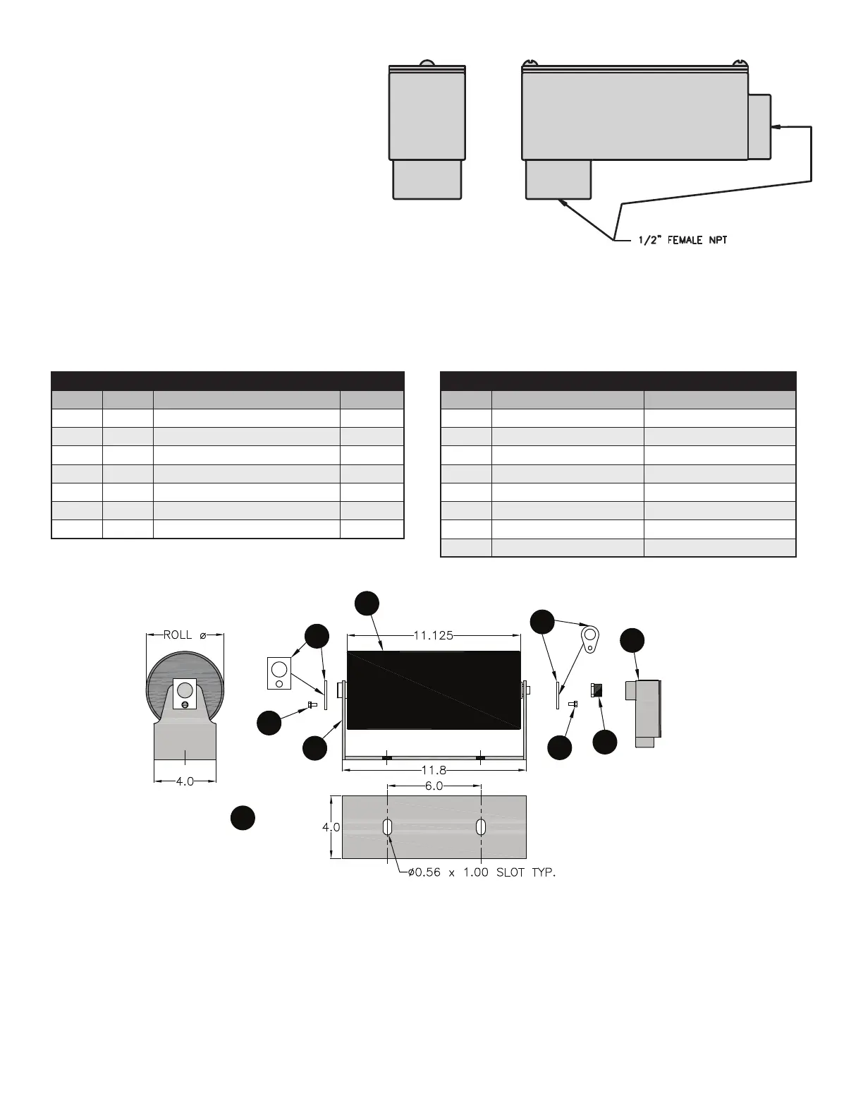
UNIVERSAL MOUNT SMART ROLL DIAGRAM & PARTS
LIST:
2
3
4
1
5
8
7
6
4
FIGURE 3.1: 90° Elbow Conduit Access Port.
ASSEMBLY COMPONENTS
ITEM QTY DESCRIPTION PART #
1 1 Smart Roll TABLE
2 1 Universal Mount Frame 38040
3 1 D End Clip 47117
4 2 #12-3/8” Self Tapping Screw 31880
5 1 B End Clip 31800
6 1 Hex Bushing 34461
7 1 90º Elbow Conduit Access Port 34452
UNIVERSAL MOUNT SMART ROLLS
ROLL Ø
ASSEMBLY PART #
ROLL ONLY PART #
5.0 SAD5UMSB – 1P SAD5TE30SB – 1P
5.0 SAD5UMSB – 2P SAD5TE30SB – 2P
5.0 SAD5UMSB – 6P SAD5TE30SB – 6P
6.0 SAD6UMSB – 1P SAD6TE30SB – 1P
6.0 SAD6UMSB – 2P SAD6TE30SB – 2P
6.0 SAD6UMSB – 6P SAD6TE30SB – 6P
5.5 SAD5UMSB – 2PL4 SAD5TE30SB – 2PL4
6.5
SAD5UMSB – 2PL4
SAD6TE30SB – 2PL4