FM Installation drawing 4500QF01-V1R0
FM Certificates FM22US0014X
FM22CA0009X
Standards: See Certificate
Marking: CL I Div 2 GP A,B,C,D T5
CL I Zone 2 AEx/Ex ec IIC T5 Gc
Temperature range -20°C ≤ Ta ≤ +60°C
AEx/Ex ec Installation Instructions
For safe installation of the 4500 series of products the following must be
observed.
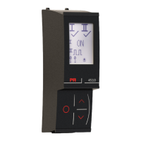
CL I Div2 GP A,B,C,D
CL I Zone 2 AEx/Ex ec IIC T5 Gc
PR
4000/9000
PR
4000/9000
PR
4000/9000
4511
4511
4511
IP 54
T
Gateway
PLC/DCS
HMI/PC
Modbus RTU
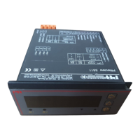
CL I Div2 GP A,B,C,D
CL I Zone 2 AEx/Ex ec IIC T5 Gc
PR
4000/9000
PR
4000/9000
PR
4000/9000
4510/
4512
IP 54
4510/
4512
4510/
4512
FM Installation Drawing
4510V100-UK 15