6
EN
- Switch: the machine features a safety switch with release coil. In the case of a
sudden power failure, the switch trips automatically and disconnects the machine
from the mains. The machine will not start even if the power supply is suddenly
restored. You need to reset the switch to start the machine again.
- Safety button: this is used to block the arm in the completely raised position.
When the button is released, the arm is blocked. This condition is required when ad-
justing the sharpening angles, when replacing and dressing the grinding wheel.
When the button is pressed, the arm is free to move. This condition is required
during the sharpening process.
If the arm is released suddenly when the machine is in use, the button trips and
blocks the arm in the raised position.
10. INTENDED USE
This machine is an electrical grinder for chains used in chain saws.
- Use the machine exclusively for the types of chains stated in the technical data
chart.
- Do not use the machine to cut or grind anything other than the chains envisaged.
- Securethemachinermlytothebenchorwall.
- The machine must not be used in corrosive or explosive environments.
- Any other use is to be considered improper.
The manufacturer is not liable for damages following improper or incorrect use of
the machine.
11. UNPACKING
The grinder is supplied already partially assembled.
12. STANDARD SUPPLY (FIG.2)
1 - Base unit 13 - Washer for screw M10
2 - Arm-motor unit 14 - Arm blocking handle
3 - Owner’s manual 15 - Arm securing nut M10
4 - Test card 16 - Operating handle
6 - Grinding wheel Ø 145x3.2x22.2 19 - Sharpening template
7 - Grinding wheel Ø 145x4.7x22.2 20 - Dressing brick
8 - Grinding wheel Ø 145x6x22.2 21 - 4 mm Allen wrench
12 - Arm securing screw M10x40 22 - 5 mm Allen wrench
13. TESTING THE GRINDING WHEEL
Hold the grinding wheel up by its central hole. Knock the edge of the grinding wheel
gently with a metal object. If it makes a numb non-metallic noise it means that
the wheel could be damaged: do NOT use it!
14. INSTALLATION
ATTENTION
Do not install the machine at eye level. You are recommended to install it at a height
ofnomorethan1.2-1.3metersofftheoor.
The machine can be bench mounted or wall mounted.
14.1 BENCH MOUNTING
- use 2 M8 screws complete with washers and nuts
(material not supplied), inserted in the securing holes F4. Make sure you position
the base unit on the bench as illustrated in the detail.
- to secure the arm-motor unit to the base unit, insert the V5
screw in the dedicated hole F5. Insert the R5 washer at the back and tighten the
knob M5.
14.2 WALL MOUNTING
- use two dowels with relative screws complete with
washers (material not supplied), inserted in the securing holes F6.
- to secure the arm-motor unit to the base unit, insert the V5
screw in the dedicated hole F5. Insert the R5 washer at the back and tighten the
nut D5.
14.3 SECURING THE OPERATING HANDLE (FIG.7)
- Completely screw the operating handle I7 on the screw V7.
15. CHAIN INFORMATION
The chain must be completely inspected before sharpening it to make sure it is
intact.
1 Top part 1 Connection link
2 Top cutting angle 2 Left cutter
3 Side cutting angle 3 Right cutter
4 Sharpening recess 4 Driving link (pulling link)
5 Depth gauge 5 Rivet
6 Bit
7 Heel
8 Rivet hole
16. CHAIN IDENTIFICATION
- Before you start to sharpen, you need to know the type of chain and the relative
adjustment angles. These characteristics are written in the owner’s manual of the
chainsawonwhichthechainisttedoronthechainpack.
- Thechainidenticationcodeisusuallywrittenonthedrivinglink.
- You can also identify the chain using a template or gauge.
- Consult the CHAIN CHART at the end of this manual.
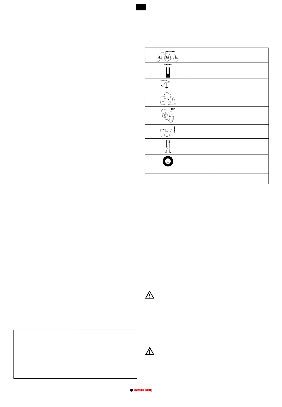
The columns in this chart provide the following information:
A
÷ 2
Chain pitch
B
Gauge
C
Top sharpening angle (vise rotation)
D
Cutting angle (arm rotation)
E
Down angle (vise inclination)
F
Gauge depth
G
Grinding wheel thickness
H
Grinding wheel code
I Oregon chain codes N Carlton chain codes
L Windsor chain codes O Stihl chain codes
M SARP chain codes P EM chain codes
16.1 INSTRUMENTAL MEASUREMENTS (FIG.13)
a - Measure the gauge depth using the suitable shape.
b - Put the template on this side and measure the chain PITCH.
c - Put the template on this side to measure the cutter length.
d - The driving link width is measured using a suitable instrument (i.e. gauge).
17. GRINDING WHEEL WARNINGS
- Use a grinding wheel suitable for the type of chain to be sharpened; consult the
chain chart at the end of the manual.
- Do not force the grinding wheel on the hub and do not alter the centering hole
diameter.Donotusegrindingwheelsthatdonottperfectlyinplace.
- Useexclusivelycleanandperfectintacthubandangetotthegrindingwheel.
- Makesuretheoutsidediametersofthehubandangeareidentical.
18. FITTING THE GRINDING WHEEL
- Loosen the screw V10 and turn the guard P10 .
- RemovethescrewV8andtheangeF8onthehub.
- Choose the grinding wheel based on the type of chain to be sharpened (column H
in chain chart).
- Insert and perfectly center the grinding wheel in the dedicated seat on the hub
.
- InserttheangeF8andtightenthescrewV8.
Ifthegrindingwheelisttedwiththeangestootight,itcouldbreakduring
use and put the operator at risk. To avoid such risk, tighten screw M6x25 to
7 Nm (if possible, check with dynamometric spanner).
- Close the guard again P10 and tighten the relative screw V10. Do not screw the
screw too tight during this job to avoid cracking the guards.
19. CHECKING THE ASSEMBLY OF THE GRINDING WHEEL
- Stand at the side of the grinding wheel, start the grinder and visually make sure
the grinding wheel does not oscillate sideways or crosswise, consequently causing
abnormal vibrations.
- If this should be the case, stop the machine immediately and check if the grinding
wheelhasbeenttedcorrectly.Ifnecessary,replacethegrindingwheelwithanother
original one.
Alwayscheckafreshlyttedgrindingwheelatworkingspeedforatleastone
minute before you start grinding, standing at a safe distance and making sure
nobody else approaches the machine.