6
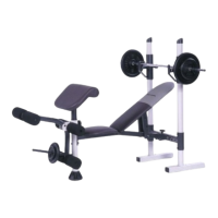
1. Before assembling the weight bench, be sure
that you have read and understand the infor-
mation in the box above.
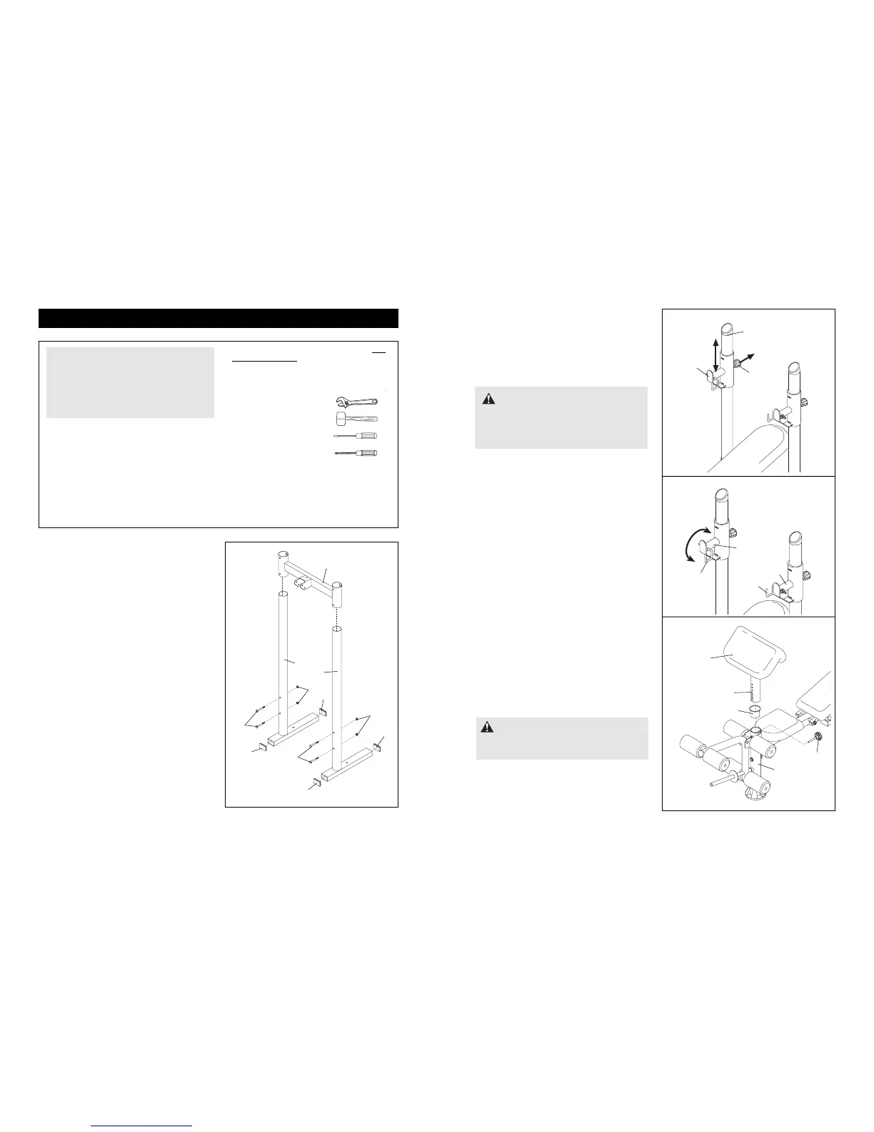
Press the four 50mm x 70mm Inner Caps (24)
into the indicated ends of the two Uprights (1).
Whilst another person holds the Crossbar (2),
orient the two Uprights (1) beneath it as shown.
Slide the Crossbar down onto the Uprights and
secure it with four M10 x 80mm Bolts (23) and
four hand-tightened M10 Nylon Locknuts (11). Do
not tighten the Nylon Locknuts yet.
1
23
23
24
24
24
1
2
1
24
11
11
Assembly
11
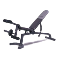
ATTACHING AND REMOVING THE CURL PAD
For some exercises, the Curl Pad (9) must be
attached to the weight bench. Insert the Plastic
Bushing (30) and the Curl Frame (8) into the Front
Leg (3), and tighten the M10 x 70mm Adjustment
Knob (29) into the Front Leg and the Curl Frame.
To remove the Curl Frame (8) from the Front Leg (3),
remove the M10 x 70mm Adjustment Knob (29) and
lift the Curl Frame out of the Front Leg.
USING THE BARBELL HOOKS
To change weights whilst your barbell (not included)
is on the Weight Rests (19), secure the barbell by
rotating the Barbell Hooks (39, 40) over the barbell.
This will reduce the possibility of the barbell tipping
whilst you are changing weights.
WARNING: When the Curl Pad (9)
is not in use, store it away from the bench so
that it will not interfere with other exercises.
9
19
19
39
40
8
30
3
29
• Assembly requires two people.
• Place all parts in a cleared area and remove the
packing materials. Do not dispose of the packing
materials until assembly is completed.
• As you assemble the weight bench, make sure all
parts are oriented as shown in the drawings.
• Tighten all parts as you assemble them, unless
instructed to do otherwise.
• For help identifying the small parts, use the Part
Identification Chart on page 5.
The following tools (not included) are required
for assembly:
• Two adjustable spanners
• One rubber mallet
• One standard screwdriver
• One phillips screwdriver
• Lubricant, such as grease or petroleum jelly,
and soapy water.
Assembly will be more convenient if you have the
following tools: A socket set, a set of open-end or
closed-end spanners or a set of ratchet spanners.
Make Things Easier for Yourself
Everything in this manual is designed to ensure
that the weight bench can be assembled suc-
cessfully by anyone. However, the weight
bench has many parts, and the assembly
process will take time. Setting aside plenty of
time will make the assembly go smoothly.
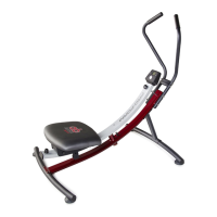
ADJUSTING THE WEIGHT RESTS
To adjust each Weight Rest (19), turn the Large
Adjustment Knob (21) counterclockwise, pull it out of
the Weight Rest, and slide the Weight Rest up or
down the Upright (1) to the desired position. Reinsert
the Large Adjustment Knob so that it locks into a hole
in the Upright and turn it clockwise until it is tight.
19
1
21
WARNING:
Always set both
Weight Rests (19) at the same height. Make
sure that the Large Adjustment Knobs (21)
are inserted completely and tightened into
the Uprights (1).