©2022 Pro-Vision Solutions, LLC. Page 10 of 56
Analog HD Wide-Angle Low Profile Camera Installation
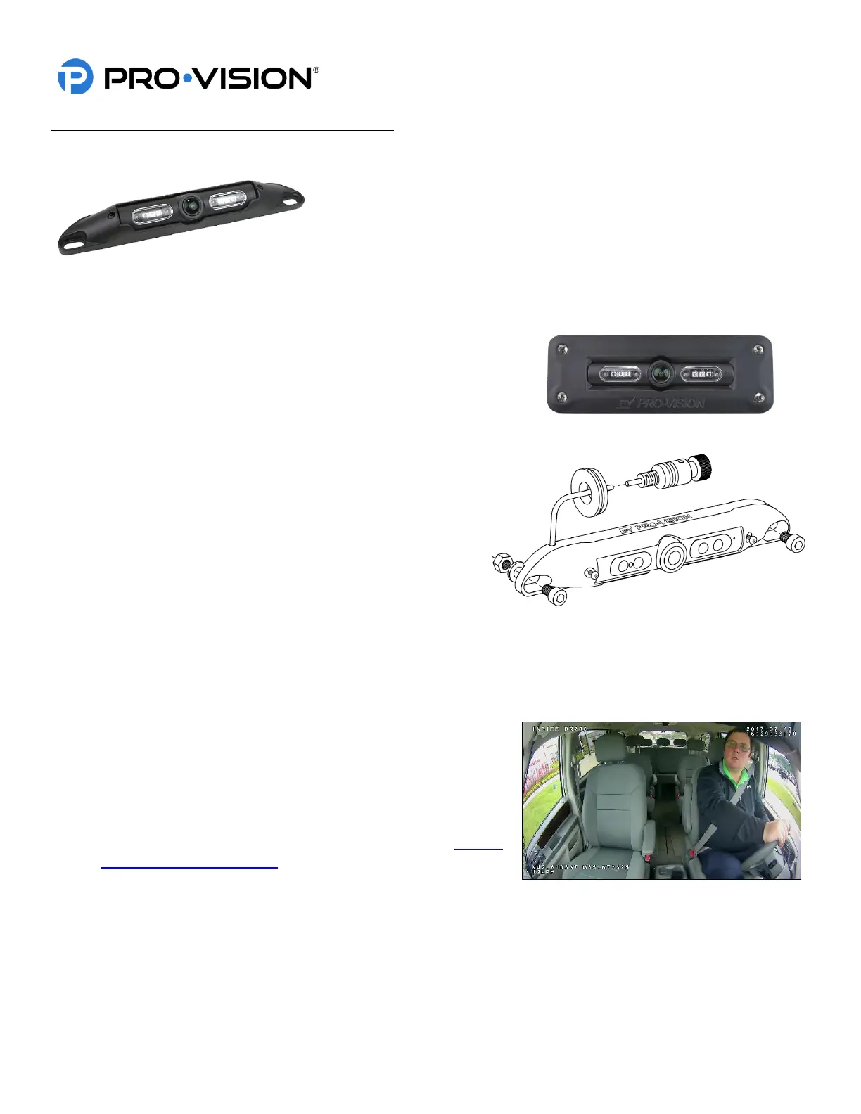
The AHD Low Profile Camera (Kit P/N: DVR-923, Camera P/N: PC-1923) is
designed to be mounted inside the vehicle for coverage of the driver,
passengers, and cargo. It has a very low-profile housing, allowing it to be
mounted to the ceiling or headliner, providing an optimal field of view. The
camera has four (4) infrared (IR) LED’s that provide illumination during low
light/dark conditions. The camera also has a microphone built into the
camera housing. The camera lens has an extremely wide 180° horizontal
and 90° vertical coverage. The camera also has an optional flush mounting
bracket (P/N: PC-1268) for applications where the camera cannot protrude.
Mounting Location:
This camera is normally used in the interior of the vehicle because of its
small size and wide field of view. The camera can only be mounted to a
horizontal surface. It is designed to be mounted directly to the mounting
surface and can adjust up and down for proper aim.
Standard Installation:
1. Locate the desired mounting location of the camera. It is
recommended to power on the DVR unit and temporarily
connect the camera to it and observe that the view in the
desired mounting location is satisfactory before
proceeding to the next step.
2. When the desired mounting location is found, mark or
measure the two (2) mounting screw hole locations in the
camera.
3. If the cable will be routed behind a vehicle panel, it is
common to drill a ¾” hole behind the camera where the cable exits the camera body. Mark and drill this hole if
needed. Remove any burrs or jagged edges from the hole to prevent damage to the cable. If surface mounting,
there is a notch in the top left of the camera for the cable to exit and then route into the gap of panel.
4. Route the camera cable into the hole and then install the camera to the marked locations from step 2. Attach the
camera with the supplied mounting hardware.
5. Route and install the extension cable(s) to the cameras final
mounting location and connect it to the camera. Leave enough
slack (typically 4”-6”) to allow removal of the camera. This will
simplify service in the future.
6. Power on the DVR unit, connect to the Wi-Fi, and view the live
camera image to properly aim it on the view page. (See Viewing
Cameras on a Smart Device for connection details) To adjust the
camera aim, loosen the two (2) small Phillips head screws on
either side of the camera assembly.
7. After the camera is aimed, tighten the two (2) Phillips’s head adjustment screws.
 Loading...