©2022 Pro-Vision Solutions, LLC. Page 11 of 56
Optional Flush Mount Installation (Requires P/N: PC-1268):
1. Remove the four (4) screws and plastic back plate from the
back of the camera and set aside.
2. Remove the camera assembly from the low-profile
aluminum housing and place it into flush mount bracket.
3. Place plastic back plate from Step 1 on flush mount bracket
and tighten all four (4) screws.
4. Power on the DVR unit, connect to the Wi-Fi, view the live camera image, and determine if the view is acceptable.
(See Viewing Cameras on a Smart Device for connection details.) If needed, the camera can be rotated up or
down by 15° in either direction.
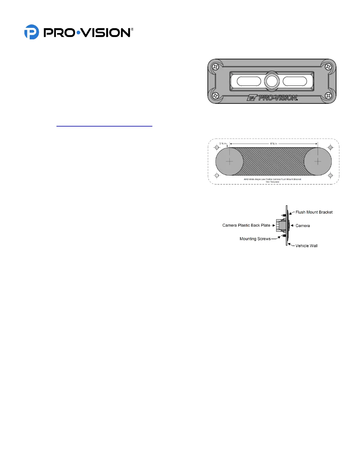
5. After verifying the camera location, use the template
included with the flush mount bracket to mark the two (2)
main slot holes.
6. Drill the two (2) main holes for the camera using a 1 3/8”
inch hole saw.
7. Use shears or a grinding tool to remove the material
between the two (2) holes.
8. Route the camera cable as desired in the newly cut slot. Place the
flush mount bracket in the slot and mark the four (4) mounting
holes.
9. Using a 1/8” drill bit, drill pilot holes at the marked four (4)
mounting holes.
10. Install the four (4) mounting screws to attach the bracket to the vehicle.