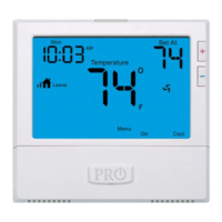
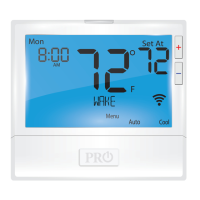
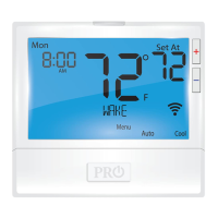
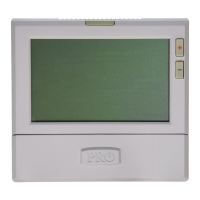
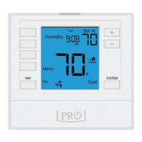
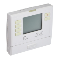
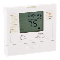
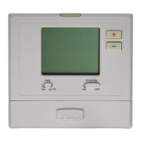
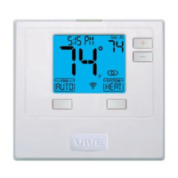
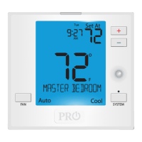
Getting to know your thermostat
Glow in the dark light button
Setpoint buttons
Program buttons
Menu button
Fan button
LCD Display
System button
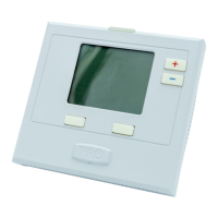
Button/battery access door
Battery cover
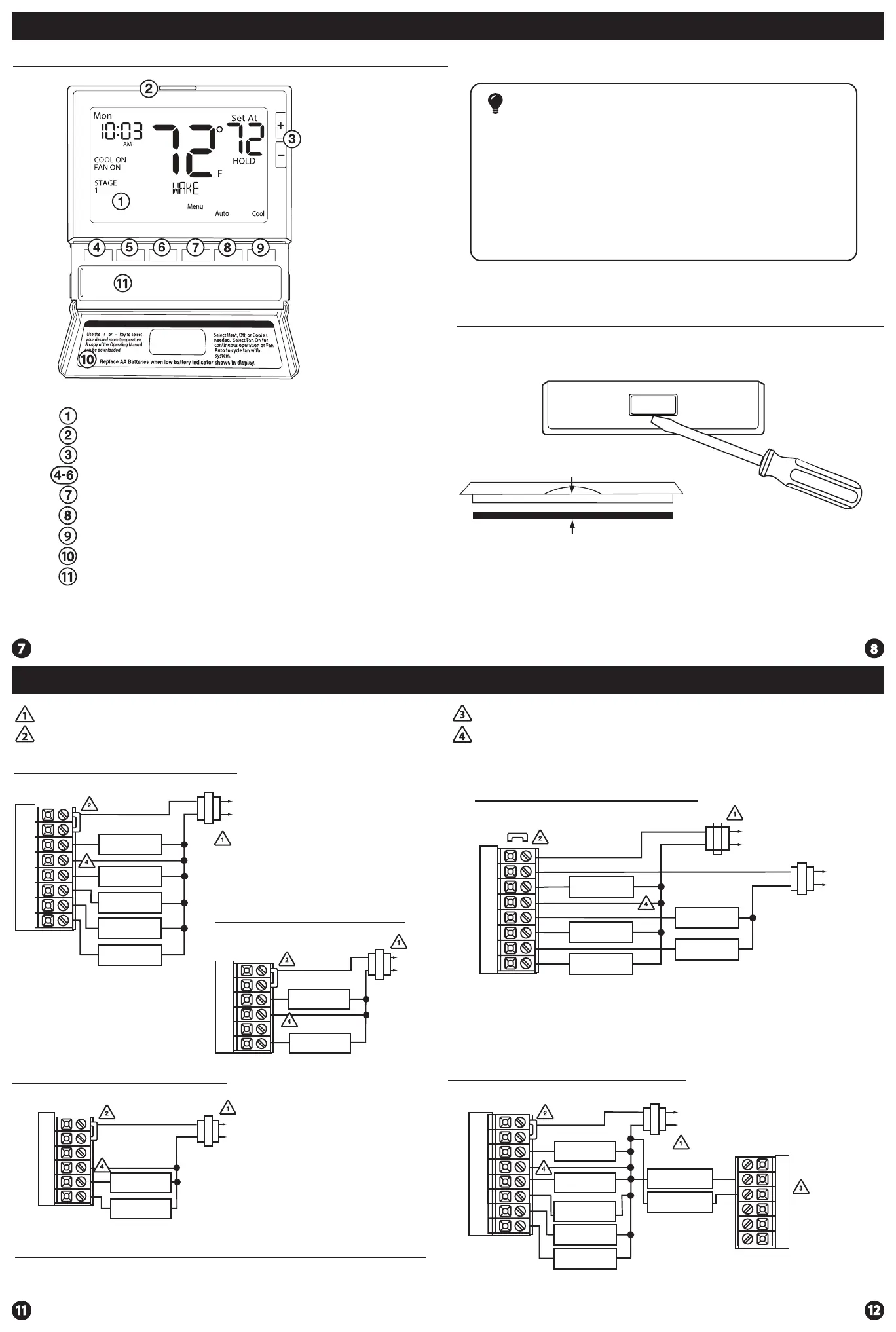
Gently slide a screwdriver into the bottom edge
of the badge. Gently turn the screwdriver counter
clockwise. The badge is held on by a magnet in the
well of the battery door. The badge should pry o
easily. DO NOT USE FORCE.
About The Badge
All of our thermostats use the same universal magnetic badge. Visit the
company website to learn more about our free private label program.
Thermostat Quick Reference
Wiring Diagrams Wiring Diagrams
Typical 2H/2C System: 1 Transformer
Typical 2H/2C System: 2 Transformer
Typical Heat Only System With Fan
Typical Cool-Only System With Fan
FAN RELAY
HEAT RELAY
RC
RH
Y
C
W/E
G
C
R
L2
L1(HOT)
FAN RELAY
COMPRESSOR
RELAY
C
R
L2
L1(HOT)
RC
RH
Y
C
G
Power supply
Factory-installed jumper. Remove only when installing on 2-transformer systems
Use either O or B terminals for changeover valve
Optional 24 VAC common connection when thermostat is used in battery power mode
W/E
REMOVE JUMPER
RC
RH
Y
C
W/E
G
W2
Y2
C
R
L2
L1(HOT)
C
R
L2
L1(HOT)
COMPRESSOR
RELAY
HEAT RELAY
FAN RELAY
Note:
In many systems with no emergency heat relay a jumper can be installed
between E and W2.
Magnet in door
Use the bevel on lower ridge
Thermostat Quick Reference
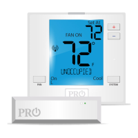
The low battery icon is displayed when the AA battery power is low. Whenever the
thermostat detects low battery voltage from the AA batteries, the low battery icon will
begin ashing on the screen for 21 days (if the batteries are not changed). If the batteries
are not changed 22 days after the thermostat detects low battery voltage, the thermostat
screen will only show the ashing battery icon until buttons are pressed. If the batteries
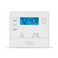
are not changed 43 days after the thermostat detects low battery voltage, the thermostat
screen will only show the ashing battery icon until buttons are pressed and the set points
will oset to 85°F/29°C in cooling and 55°F/13°C in heating. At this stage, set point changes
can be made temporarily but, the set points will change back to defaulted values after a
4-hour period. The thermostat will continue to perform this low battery ashing,
temperature oset condition until the internal voltage threshold is reached. When the
thermostat internal voltage threshold is reached, all relays will be opened and the
thermostat will become inoperable until new batteries are installed.
Important
HEAT RELAY 2
COMPRESSOR
RELAY 2
Typical Cool-Only System With Fan
RC
RH
Y
C
W/E
G
W2
Y2
COMPRESSOR
RELAY
FAN RELAY
HEAT RELAY 2
COMPRESSOR
RELAY 2
HEAT RELAY
C
R
L2
L1(HOT)
Typical 3H/2C or 2H/1C Heat Pump System
RC
RH
Y
C
W/E
G
W2
Y2
COMPRESSOR
RELAY
FAN RELAY
AUXILIARY
HEAT RELAY
COMPRESSOR
RELAY 2
EMERGENCY
HEAT RELAY
COOL CHANGE
OVER VALVE
HEAT CHANGE
OVER VALVE
C
R
L2
L1(HOT)
O
B