www.usaprocom.com
200233-01B18
OPERATION
TO TURN OFF GAS TO APPLIANCE
1. Remove lower front panel.
2. Follow steps 1 through 5 under Lighting
Instructions, page 16 or 17.
3. With control knob pressed in, strike match.
Hold match to pilot until pilot lights.
4. Keep control knob pressed in for 30 sec-
onds after lighting pilot. After 30 seconds,
release control knob. Follow step 8 under
Lighting Instructions, page 16 or 17.
5. Replace lower front panel.
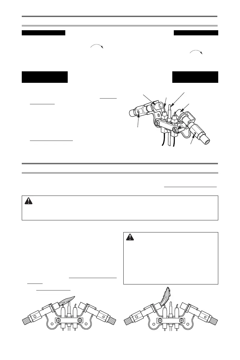
Figure 21 - PIlot Assembly
Shutting Off Heater
1. Turn control knob clockwise to the
OFF position.
2. Turn off all electric power to the appliance
if service is to be performed.
Shutting off burner only
(pilot stays lit)
Turn control knob clockwise to the
PILOT position.
MANUAL LIGHTING PROCEDURE
(ALL MODELS)
INSPECTING HEATER
IMPORTANT: Owner’s should check pilot ame pattern and burner ame pattern often.
Incorrect ame patterns indicate the need for cleaning (see Care and Maintenance,
page 19) or service.
WARNING: Only a qualied service person should service and
repair heater. This includes maintenance requiring replacement or
alteration of components.
PILOT FLAME PATTERN
Figure 22 - Correct Pilot Flame Pattern Figure 23 - Incorrect Pilot Flame Pattern
Figure 22 shows a correct pilot ame pattern.
Figure 23 shows an incorrect pilot ame pat-
tern. The incorrect pilot ame is not touching
the thermocouple. This will cause the ther-
mocouple to cool, which shuts the heater off.
If pilot ame pattern is incorrect, as shown
in Figure 23
• turn heater off (see To Turn Off Gas to Ap-
pliance, page 17 or 18)
• see Troubleshooting pages 20 through 24.
WARNING: If yellow tipping
occurs, your heater could pro-
duce increased levels of carbon
monoxide. If the burner ame
pattern shows yellow tipping,
follow instructions at bottom of
this page.
Pilot Air
Inlet Hole
Natural Gas
Burner
Propane/LP
Gas Burner
Thermocouple
Pilot Air Inlet Hole
Ignitor
Electrode
NG
3-3.5" WC
Natural Gas
Shown
LP
8-11" WC
NG
3-3.5" WC
Natural Gas
Shown
LP
8-11" WC