10
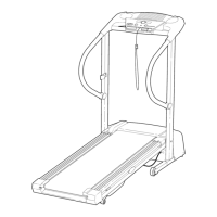
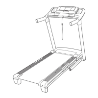
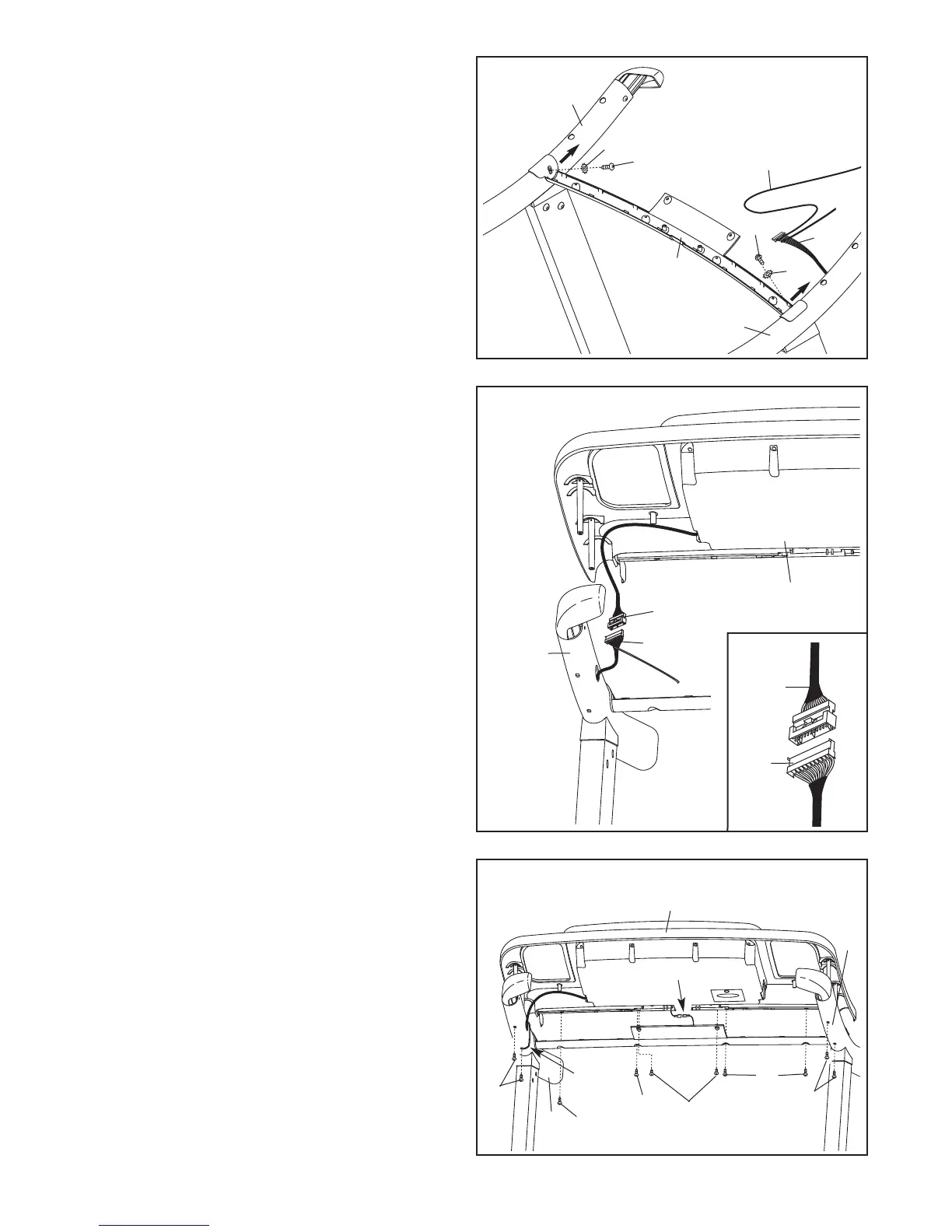
12. With the help of a second person, hold the con-
sole assembly near the Right Handrail (33) and
the Left Handrail (not shown).
Connect the Upright Wire (38) to the Console
Wire.
See the inset drawing. The connectors
should slide together easily and snap into
place. If they do not, turn one connector and try
again. IF THE CONNECTORS ARE NOT CON-
NECTED PROPERLY, THE CONSOLE MAY
BE DAMAGED WHEN YOU TURN ON THE
POWER. Insert the connectors and the excess
wire into the Right Handrail (33).
Console
Assembly
12
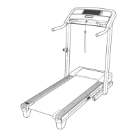
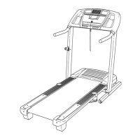
13.
Connect the console ground wire to the handrail
ground wire.
Set the console assembly on the Right Handrail
(33) and Left Handrail (35). Make sure that the
wire harnesses are not pinched. Attach the
console assembly with two #8 x 1/2" Screws (1),
four #8 x 3/4" Screws (12), and four #8 x 1/2"
Washer Head Screws (112). Start all the
Screws before tightening any of them.
Cut the plastic tie from the Right Handrail (33).
See steps 5 and 7. Firmly tighten the four 3/8" x
4" Bolts (6).
Console
Assembly
Ground Wires
13
Console
Wire
Console
Wire
38
38
33
12
12
Plastic
Tie
112
112
1
12
35
33
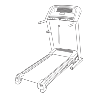
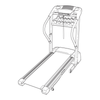
11. Set the Pulse Bar Bottom (95) on the Left
H
andrail (35) and the Right Handrail (33). Press
the Pulse Bar Bottom forward as you tighten two
#10 x 3/4" Screws (5) with two #10 Star
Washers (10) into the Handrails.
Remove the long tie from the Upright Wire (38).
1
1
95
5
5
38
33
35
10
10
L
ong Tie