USER’S MANUAL. PROMAX-25
09/2004 Page 33
English
APPENDIX B.- PRINCIPLE OF QAM MODULATION.
THE CONSTELLATION DIAGRAM
The modulation process implies to transfer the information contained in a signal
to a high frequency carrier. Modulation QAM, in concrete uses modulation in quadrature
consisting of two carriers each one of the same frequency, one called-I (in phase) and
another out of phase 90° called Q (quadrature).
Each one of them is modulated in amplitude and phase by a portion of the
digital input signal. The two modulated signals are combined then and they are
transmitted as a single waveform. The receiver only needs to invert the process for
generating a digital output that can be processed to produce images or another useful
information also.
The number of levels used in the modulation of each carrier determines the
number of possible symbols and, consequently, the number of bits that can be
transmitted in a certain bandwidth. The DVB-C standard allows 5 types of modulation:
16 QAM, 32 QAM, 64 QAM, 128 QAM and 256 QAM.
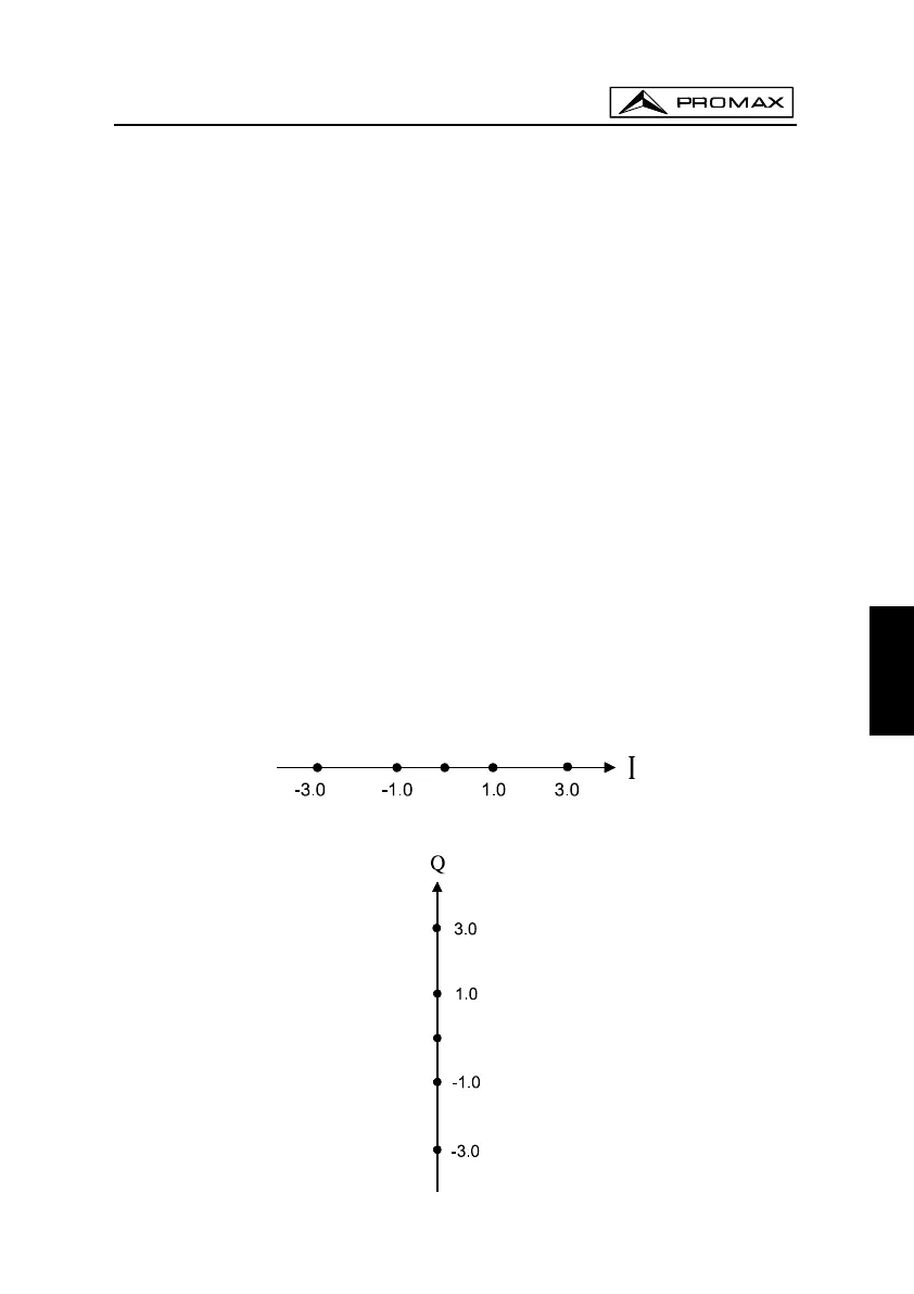
For example, if four amplitude levels are applied to each one of the carriers,
each signal could reach the value of -3.0, -1.0, +1.0, +3.0 at a given instant in time, so
we have 16 possible combinations. This is known as 16 QAM. Extending the previous
exposition to four amplitudes, it allow us to generate 8 states for each carrier and 64
possible combinations (64 QAM).
These digital signals can be visualized graphically by means of the
Constellation Diagram. If one imagines on an axis the possible states of the first
carrier (signal-I or signal in phase) we would obtain the image in figure 24.
Figure 24.- Signal-I states
Figure 25.- Signal-Q states