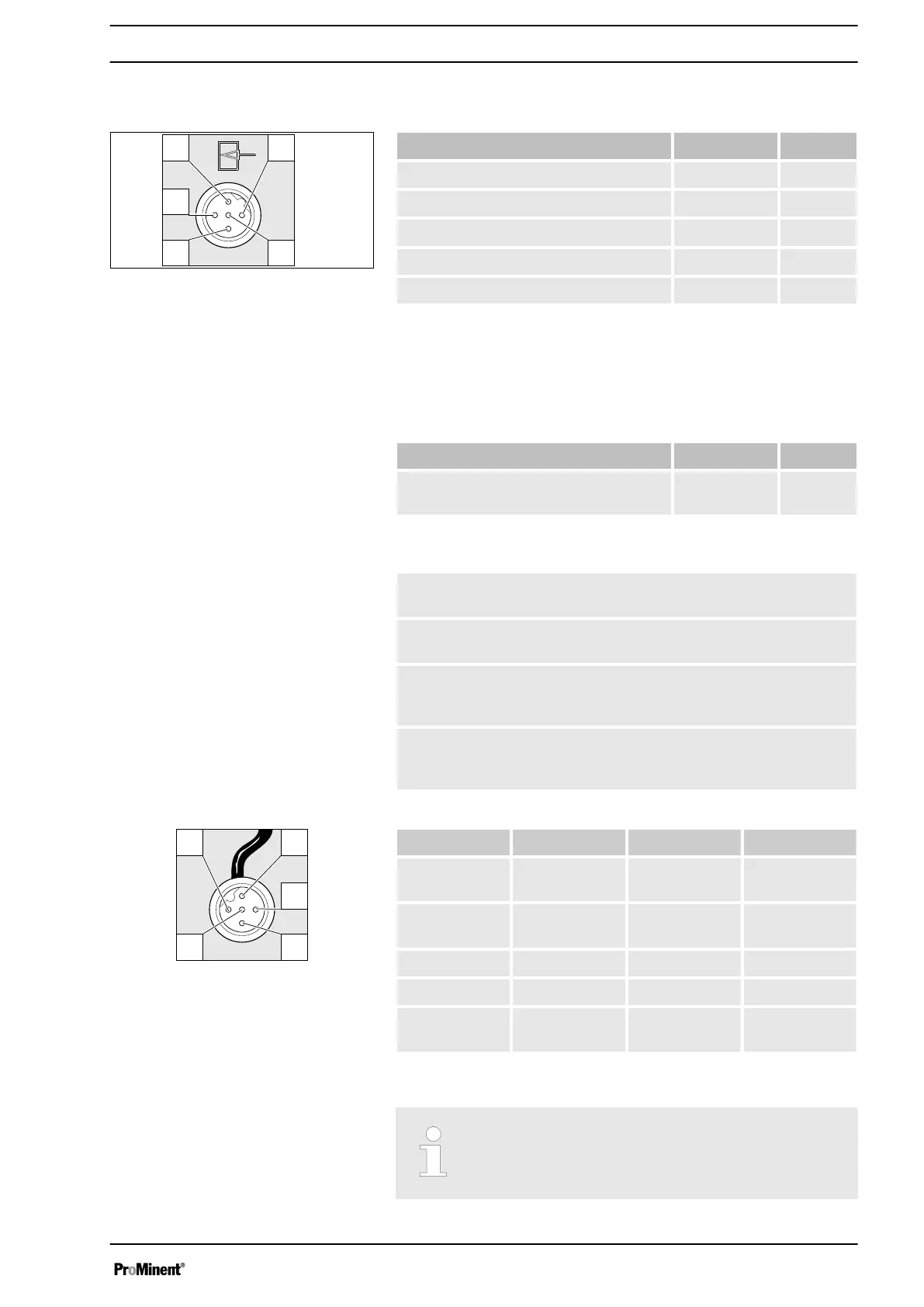
Electrical interface for pin 1 "Pause" - pin 2 "External contact" - pin
5 "Auxiliary frequency"
Data Value Unit
Voltage with open contacts 5 V
Input resistance 10 kΩ
Max. pulse frequency 25 pulse/s
Min. pulse duration 20 ms
Min. pause between pulses 3 ms
Control via:
n potential-free contact (load: 0.5 mA at 5 V) or
n Semiconductor switch (residual voltage < 0.7 V)
Electrical interface for pin 3 "mA input" (with identity code charac‐
teristic "Control version": A - "External Analogue")
Data Value Unit
Input apparent ohmic resistance,
approx.
120 Ω
Tab. 1: Behaviour of the pump
At approx. 0.1 mA (4.1 mA) the metering pump makes its first
metering stroke.
At approx. 19.9 mA the pump moves to continuous operation at
180 strokes / min .
With current signals above 23 mA, the red fault indicator lights
up, the pump stops and any fault indicating relay fitted switches
(a fault is pending).
Only with 4...20 mA: With current signals below 3.8 mA, the red
fault indicator lights up, the pump stops and any fault indicating
relay fitted switches (Fault
for example with a cable break).
Pin Function 5-wire cable 2-wire cable
1 Pause brown bridged at pin
4
2 External con‐
tact
white brown
3 mA input* blue -
4 Earth GND black white
5 Auxiliary fre‐
quency
grey -
* with identity code characteristic "Control version": A - "External
Analogue"
Refer to the functional description for the hierarchy
of functions and operating modes.
Fig. 9: Pump assignment
Fig. 10: Cable assignment
Electrical installation
33




 To Next Page