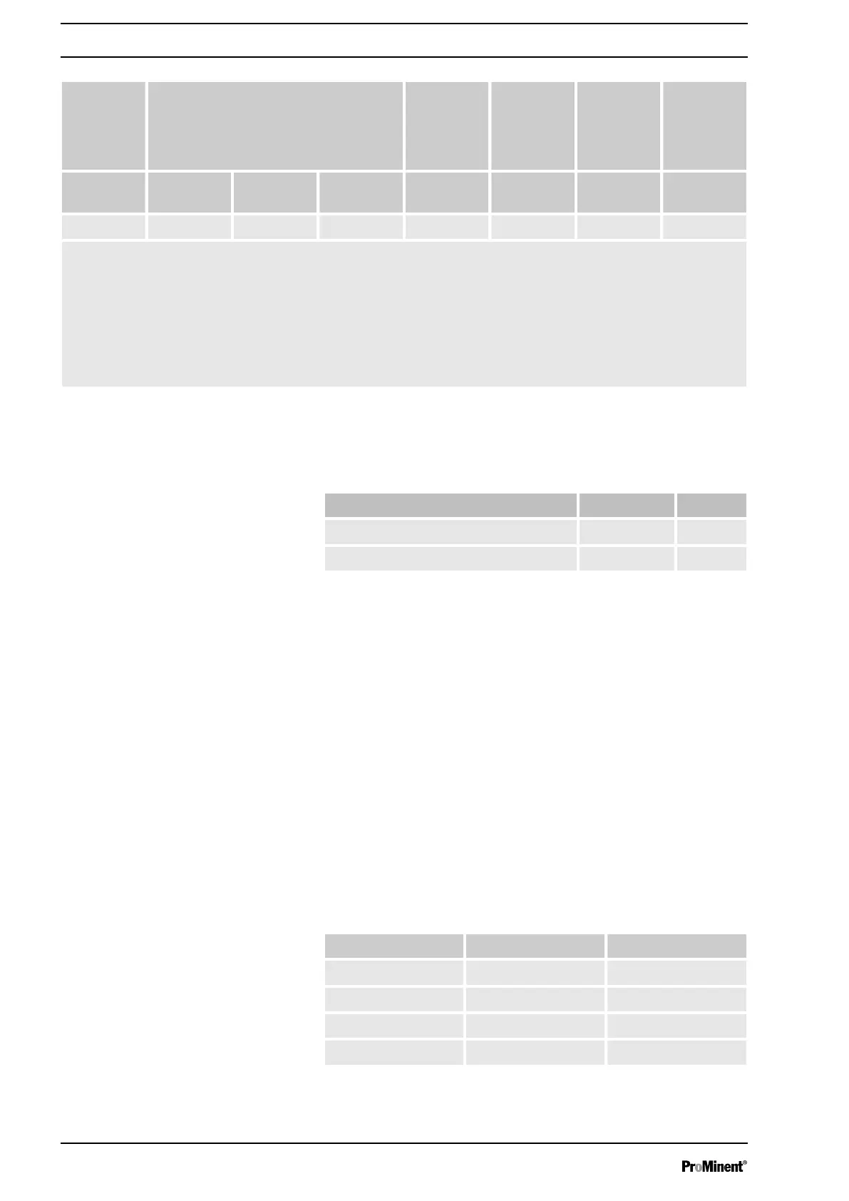
Type Pump capacity
at maximum back pressure
Connector
size
outer Æ x
inner Æ
Suction lift* Priming
lift**
Max. pri‐
ming pres‐
sure on the
suction
side
1
Beta b bar l/h ml/stroke mm m water
column
m water
column
bar
0713 7 9.5 0.88 8x5 3.0 2.0 3.5
The stated performance data represents minimum values calculated using water as the medium at 20 °C.
* Suction lift with a filled suction line and filled liquid end.
** Priming lifts with clean and moist valves. Priming lift at
100% stroke length and free drain or opened vent
valve.
1
The pressure on the discharge side needs to be at least 1.5 bar higher than the pressure on the suction
side. We therefore recommend installing a back pressure valve on the discharge side to adjust the
increased pressure. This will avoid excess pumping.
16.2 Accuracy
16.2.1
Standard Liquid End
Data Value Unit
Capacity range of the series -5 ... +10 % *
Reproducibility ±2 % **
* - at max. stroke length and max. operating pressure for all
material versions
** - at constant conditions and min. 30 % stroke length
16.2.2 Self-Bleeding Liquid End
As the self-bleeding liquid end is used with outgassing media and
when operating with air bubbles, no dosing accuracy or reproduci‐
bility can be provided.
The recommended minimum stroke length with self-bleeding
dosing pumps is 50 %.
16.3
Viscosity
The liquid ends are suitable for the following viscosity ranges:
Version Range Unit
standard 0 ... 200 mPas
With valve springs 200 ... 500 mPas
Self-bleeding (SEK) 0 ... 50 mPas
HV (highly viscous) 500 ... 3000* mPas
* Only when the installation is correctly adjusted
Technical data
58




 To Next Page