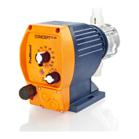
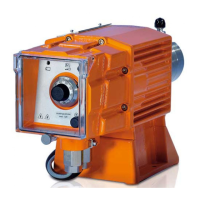
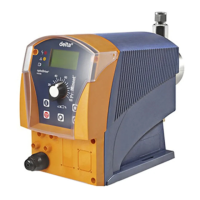
14 Installation instructions for External + Level retrofit kit
CNPb (Part no. 1022099)
Connector for external control (External oper‐
ating mode)
Scope of delivery
1 cable, 2 m; 1 cable threaded connector; 1
nut; 2 plugs; 1 Torx key, TX9
A contact or an electronic switch (contact con‐
trol, e.g. contact water meter) can be con‐
nected to the 3-wire cable for the external con‐
trol of the pump. The pump reacts to the
contact closing. The pump reacts to the contact
opening with the Pause function.
Installation
WARNING!
– Ensure that only trained and author‐
ised personnel install the retrofit kit.
–
Disconnect the pump from the mains
power supply and secure to prevent
switching on again.
External control connectors
Colour Function
GND black
Contact blue
Pause brown
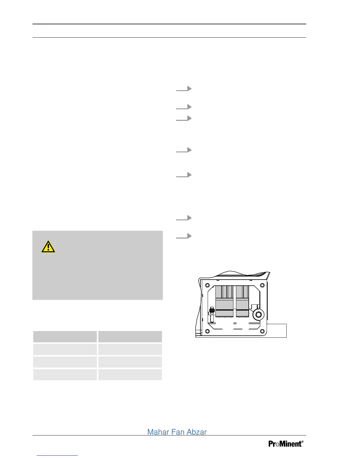
1. Unscrew the cover at the bottom right
on the front of the pump.
2. Punch open the marked openings.
3. Push the nut into each recess on the
inside of the cover and tighten the lower
part of the cable screw connectors to
make them watertight.
4. Thread the external cable and the suc‐
tion lance cable through a threaded
cable connector.
5. Connect the plugs to the ends of the
cables.
To do so, push a screwdriver
(0.4x2.5x75 mm) into the one hole and
guide the cable end into the other hole.
6. Insert the plugs into the respective
recesses on the PCB in the pump.
7. Screw the cover back onto the pump
and tighten the threaded cable connec‐
tors until they are watertight.