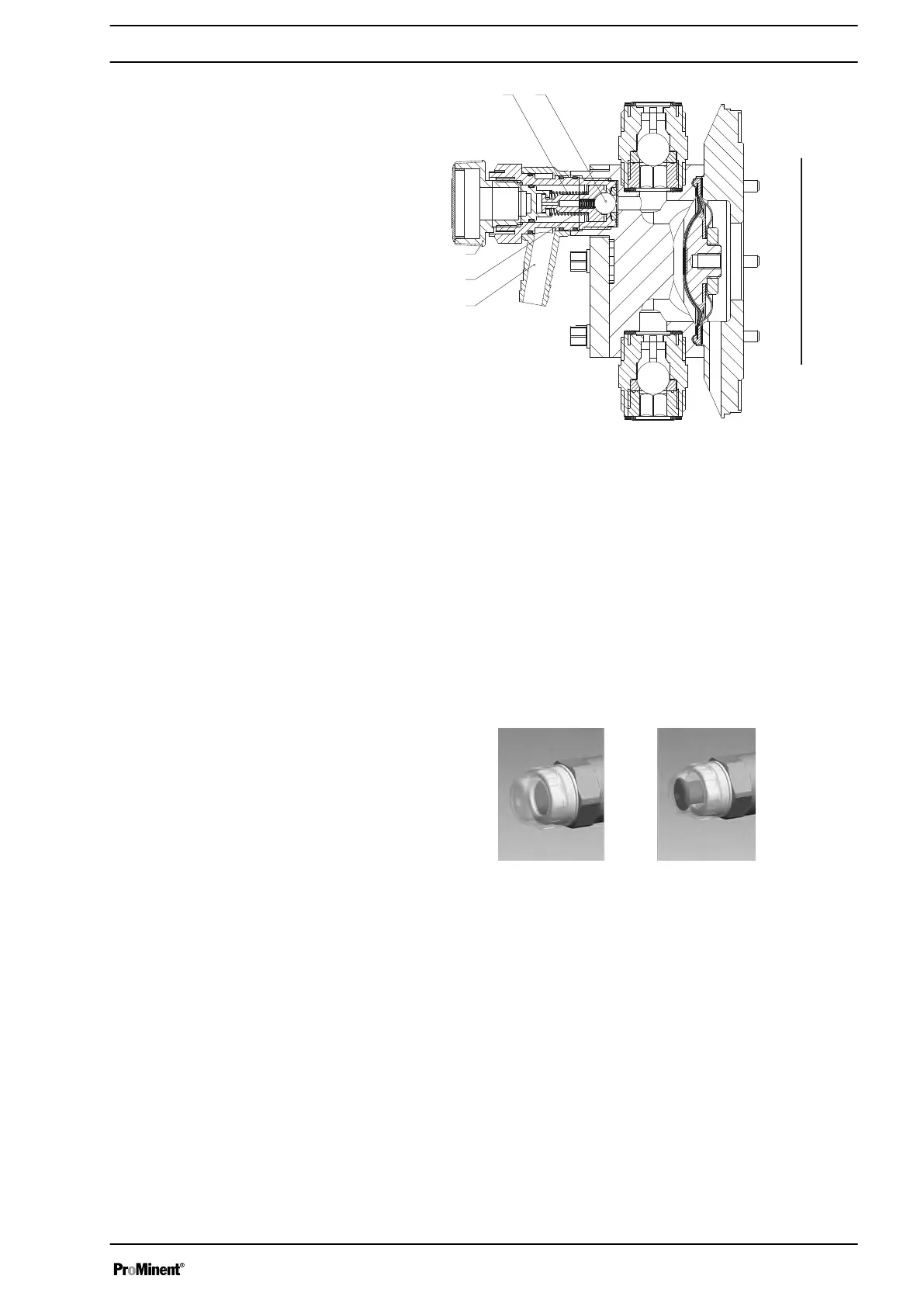
Fig. 8: Integral relief valve
1 Spring, large
2 Ball
3 Rotary dial
4 Spring, small
5 Hose connection
5.4 Multi-layer safety diaphragm
With visual diaphragm rupture sensors, in the event of a diaphragm rup‐
ture, the lowered red cylinder (6) springs forward beneath the transparent
cover (7) so that it then becomes clearly visible - see Fig. 9.
With the
electrical diaphragm rupture sensor, a switch is switched. A sig‐
nalling device must be connected to signal the diaphragm rupture.
Fig. 9: Visual diaphragm rupture sensor, triggered and untriggered
Functional description
15