EasyManuals Logo

Protectowire FiberSystem 8000 User Manual

Default Icon
50 pages
To Next Page IconTo Next Page
To Previous Page IconTo Previous Page
Page #21 background imageLoading...
Page #21 background image
Getting Started
Connecting to the Output Relays and Input Lines
The FIBERSYSTEM 8000 provides one fault relay and 43
alarm relay outputs (dry contacts) that are capable of notifying
the user of
alarm conditions.
The fault relay is normally closed and in the event of an
instrument failure or power outage open.
The alarm relays are normally open and in the event of an
alarm condition the contacts will be closed.
Reverse logic can also be programmed. The resulting ability to
switch between these two states provides several options for the
user. For example, the output can be used to operate external
audible alarms or warning lamps.
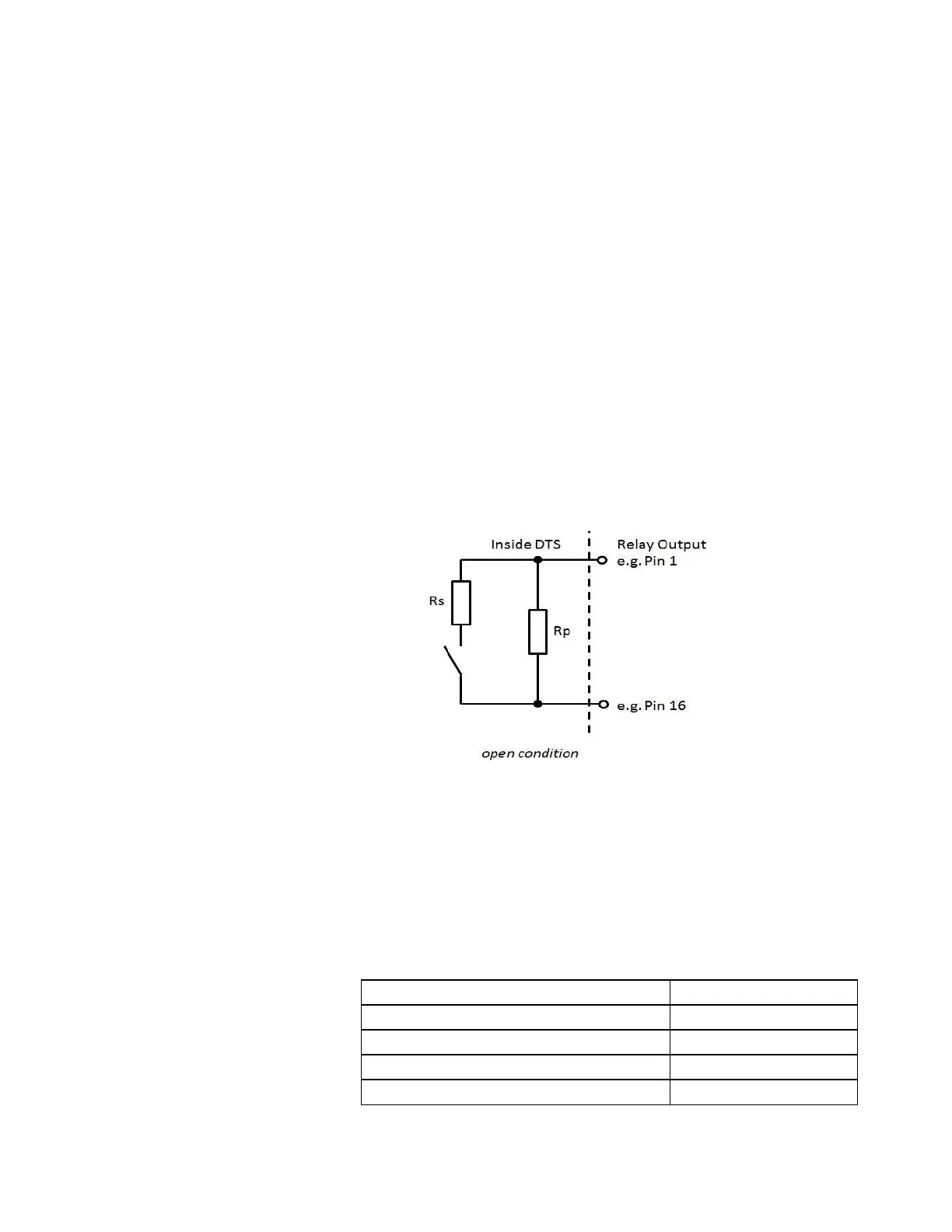
Each relay circuit consists of an additional serial and parallel
resistor as on the figure below.
Available order options:
Standard: Rs = 0 Ohm and Rp = unequipped
Equipped (on request): 1k / 10k with Rs = 1 kOhm and Rp =
10 kOhm
High density relay board with 43+1 outputs (Option-051)
Standard (without Rp and Rs = 0 Ohm):
The Protectowire Company, Inc.
FIBERSYSTEM 8000 - Linear Heat
Series
21
Programmable relay outputs
44 ( 22 per connector)
Output connectors
2
Connector type
SUB-D 44pin female
Voltage range
Max. 30 V DC
Current range
Max. 1 A DC

Questions and Answers:

Question and Answer IconNeed help?

Do you have a question about the Protectowire FiberSystem 8000 and is the answer not in the manual?

Protectowire FiberSystem 8000 Specifications

General IconGeneral
BrandProtectowire
ModelFiberSystem 8000
CategoryController
LanguageEnglish