P2_GEPARD_installer manual_ work basis_EN_02 - 03/10 - protherm
- 14 -
INSTALATION
Regulations 7.1
The type MOV is designed for combustion gases to be removed
and discharged into a chimney (through a chimney inlet) with
a minimum stabilised thrust of 2 Pa. The boiler is connected to
the chimney inlet by a fl ue of a diameter corresponding to the
size of the boiler’s gas exhaust outlet. It is forbidden to place
inside the combustion gases exhaust ducting any objects which
impair the combustion gases fl ow (e.g. various types of heat
exchangers to utilise their residual heat). The combustion gases
exhaust ducting is not part of the boiler accessories.
Construction of the combustion gases exhaust ducting as well
as that of the chimney must comply with relevant requirements.
Compliance with the requirements specifi ed by these standards
will prevent undesirable phenomena from occurring, such as
excessive cooling of the combustion gases, penetration of
dampness into brickwork and fl uctuations in the chimney thrust,
and thus prevent undesirable effects on the boiler’s functioning.
The boiler takes combustion air from the space in which
it is installed. Air must be supplied in suffi cient quantity in
accordance with applicable regulations.
Venting of exhaust and drawing in of combustion air for the
MTV type is done only through designated pipes.
The level sections of the piping slope at a gradient suffi cient to
let the condensation drain towards an outside area or towards
a receptacle designed to draw off condensation. To achieve
this, the elbow joint may be gently bent away from the straight
section. The upright sections of the piping are always fi tted with
devices to draw off condensate. The devices for drawing off the
condensate are installed where possible close to the passage
where the exhaust exits the boiler. Breakdowns caused by
leaking condensate are not covered by the boiler warranty.
Description exhausting kits7.2
Methods of air and fl ue gas ducting 7.2.1
(according to STN EN 483) and permitted
piping lengths
If not described otherwise for the individual following methods
of placing coaxial pipe routes and their drainages, the piping
lengths (from connection at the boiler to the drainage) can be
set as in the following cases.
Note: One Em is considered as either a 1 m direct section or
one 90° joint.
Caution: If the lengths described for individual types are
exceeded, the exhaust diffuser (orifi ce) must be removed from
the ventilator drain.
The following methods of air intake and exhaust venting are
recommended for the boiler:
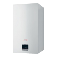
The C7.2.2
12
method (MTV)
Level routes and level venting into an open area.
Length of fume ducting (23 MTV):
60 / 100: min. 0.3 m (with one 90° joint), max. 3 m (with one -
90° joint).If the total fume ducting length is more than 0.5 m,
the diffuser with a diameter of 39 mm must be removed.
80 / 125: min. 0.5 m (with one 90° joint), max. 9 m (with one -
90° joint).If the total fume ducting length is more than 1 m,
the diffuser with a diameter of 39 mm must be removed.
An example of a level coaxial pipe route: version C
12
(complies
with STN EN 483)
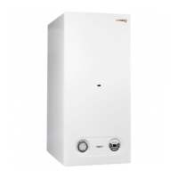
The C7.2.3
32
method (MTV)
Vertical routes and vertical venting into an open space.
Length of fume ducting (23 MTV):
60 / 100: min. 1 m (with one 90° joint), max. 4 m (with one -
90° joint). If the total fume ducting length is more than 1.5 m,
the diffuser with a diameter of 39 mm must be removed.
80 / 125: min. 1 m (with one 90° joint), max. 10 m (with one -
90° joint). If the total fume ducting length is more than 1.5 m,
the diffuser with a diameter of 39 mm must be removed.
An example of a vertical coaxial pipe route: version C
32
(complies with STN EN 483)
The C7.2.4
42
method (MTV)
Connecting to a double shared chimney.
Double piping from independent boilers (independent routes)
can feed into shared chimneys; the transport capacity of the
chimney is judged according to the manufacturer’s data on the
chimney. If the pipes are set into the chimney in two directions
and vertically aligned, there must be a vertical separation
between the outlets of at least 0.45 m. Where two outlets vent
towards each other, they must be separated by a minimum
vertical distance of 0.6 m. The exhaust piping into the shared