P2_GEPARD_installer manual_ work basis_EN_02 - 03/10 - protherm
- 8 -
INSTALATION
INSTALLATION
Location of equipment4
Location4.1
Instructions4.1.1
Before you choose a location for placement of equipment,
carefully consult safety warnings and instructions in the user
manual and installation guide.
Make sure the wall on which you installed the device, a •
suffi ciently strong structure to hold the weight of equipment.
Ensure that the area in which the device installed, big •
enough for its installation and that was around him a large
enough space. This allows access and control of water
mains, gas and ventilation (see Chapter clearance).
Explain the requirements of the user equipment.•
Clearance4.2
The minimum working (unhindered) space in close proximity
to the boiler must be such that the boiler can be worked with
easily and safely with bare hands and with the usual hand tools;
we recommend a minimum distance of 300 mm from up and
under, 10 mm from side and a minimum of 600 mm in front of
the boiler.
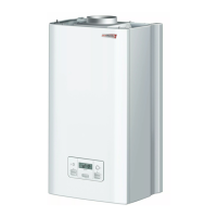
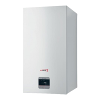
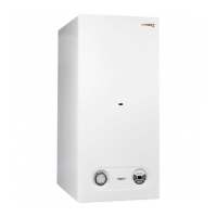
Boiler installation 5
Contents of delivery5.1
Contents of delivery
1 boiler
2 draw bar
3 exhaust gas diffuser (only for 23 MTV)
4 sealing
5 template
6 butt-end of water intake
7 butt-end of outlet valve
8 service manual
9 warranty
Check the contents of the packaging.•
Recommendations before you install5.2
Nominal pipe internal diameter is chosen in the usual way,
using the pump characteristic. Distribution pipes are designed
according to the requirements for the system performance, not
according to the boiler’s maximum output. However, measures
must be taken in order to ensure suffi cient fl ow so that the water
temperature difference in the supply and the return pipe is less
than or equal to 20˚C. Minimum fl ow must be 400 l/h.
The piping system construction must prevent air bubbles from
developing, making permanent bleeding of the system easier.
Bleeding valves should be situated on all high points of the
system and on all radiators.
It is recommended to install upstream the boiler a set of heating
water, hot water and gas isolation valves.
It is recommended to install upstream the boiler a set of heating
water, hot water and gas isolation valves.
At the lowest point of the heating system we recommend
installation of an exhaust valve, which shall also serve for fi lling
of the heating system.
Before fi nal installation of the boiler, the heating distribution
system pipes must be fl ushed a few times with pressurised
water. In old, already used systems, the fl ushing must be done
in the direction opposite to the fl owing heating water.
Important: Before connecting the boiler to the heating system,
remove the plastic plugs located inside all connection outlets.
Before installing a new boiler, it is essential to clean the
system thoroughly. In old systems it is necessary to remove all
sludge settled at the bottom of radiators (predominantly gravity
system).
In new systems it is necessary to remove all conservation
material used by majority of radiator manufacturers.
It is recommended to install upstream the boiler (i.e. on the
heating water return pipe) a sludge separator. The sludge
separator should be constructed in such a way that it is easy to
empty at regular time intervals without the necessity to drain a
large quantity of water from the heating system. The separator
can be combined with a fi lter, but a fi lter with a sieve alone is
not suffi cient protection. The fi lter and sludge separator must be
checked and cleaned regularly.
During reconstructions, in adverse building arrangements
and so on, the boiler may be connected to the CH heating
system, the HW system and the gas inlet with fl exible elements
(hoses), but only those designated for this purpose. If fl exible
elements are used, these should be as short as possible and
must be protected from mechanical and chemical stresses and
damages. It must also be ensured that before the end of their
life cycle or reliability in maintaining their parameters (according
to their manufacturers’ data) they are always replaced by new
ones.
Note: The boiler includes fi lter which is situated below the HW
fl ow sensor. You have to take out the HW fl ow sensor with fi lter
to clean up the fi lter.