PRO-VISION® Video Systems
40 provisionusa.com
17. Connect the camera connector to the cable running to the DVR unit, if it is not yet installed, install
the cable at this time and then continue to step 9.
18. Hold the camera ball and feed any excess cable through the hole or cable grove in the mounted
base until the camera ball is resting on the center of the rubber gasket.
19. Place the camera housing and then the locking ring over the camera ball. Ensure that the three
(3) mounting screw holes on the locking ring align with the holes in the mounting base.
20. Using a 2mm Allen wrench, begin to tighten each of the three (3) screws; leave the screws
slightly loose to allow the camera ball to freely move until the final camera aim is completed.
21. Power on the DVR unit and connect to the Wi-Fi to view the live camera image to properly aim it
on the view page. (See Viewing Cameras on a Smart Device for connection details)
22. When finished aiming, fully tighten the three (3) assembly screws.
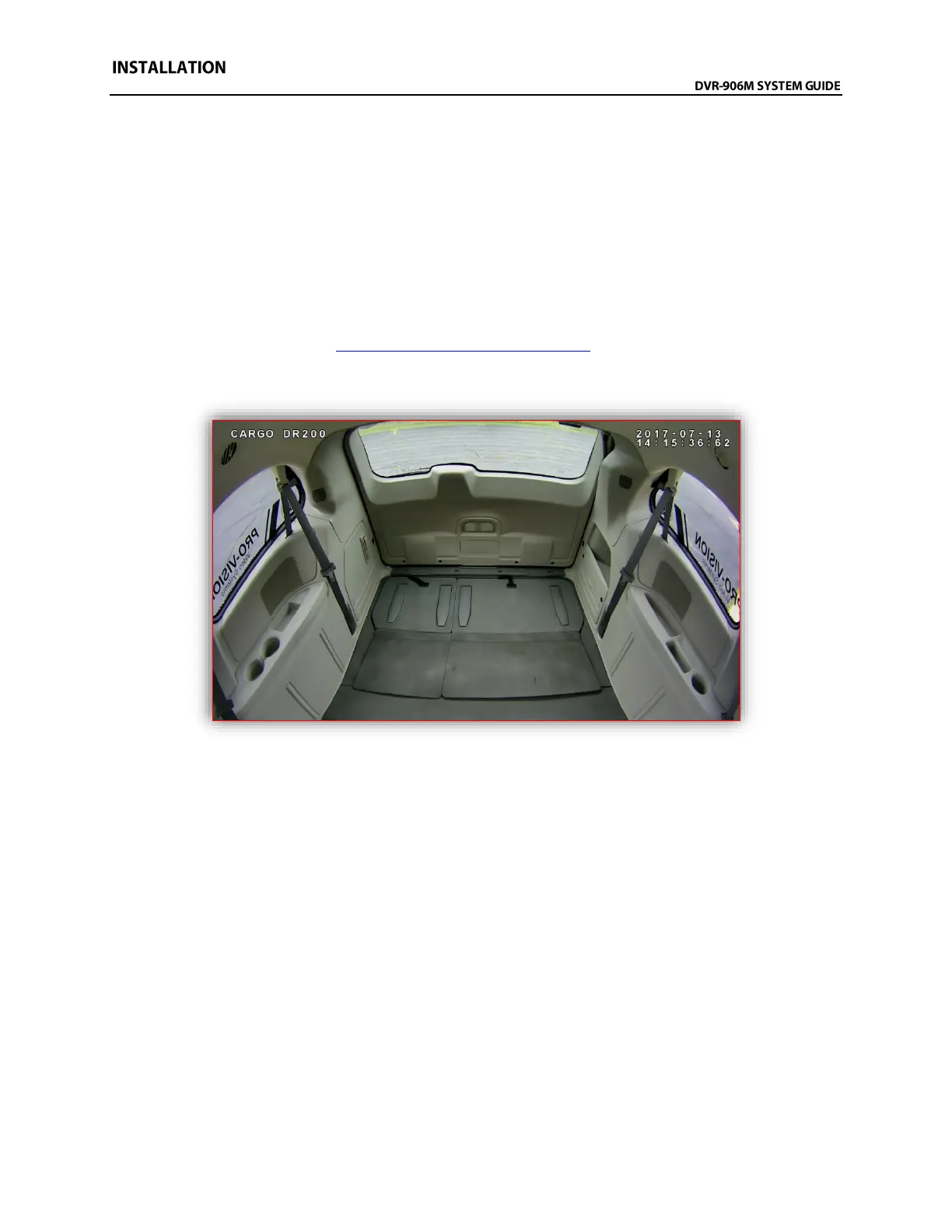
Example view of the cargo area of a Dodge Ram Cargo Minivan