PT200MI instruction manual 28
Command input PT200MI response Description
KEY ON<CR><LF> YES<CR><LF> or NO ? <CR><LF> Key protection on
(key function inhibit).
KEY OFF<CR><LF> YES<CR><LF> or NO ? <CR><LF> Key protection off
(key function enabled).
PROG<CR><LF> Continuous weight output stops Weight output in command mode.
CONT<CR><LF> Continuous weight output starts Weight output in continuous mode.
FUNC<CR><LF> Z.TRACK T=[num]<CR><LF> Enter function setting mode.
CAL<CR><LF> CAL ZERO<CR><LF> Enter calibration setting mode.
CAL 1<CR><LF> CAL ZERO<CR><LF> Enter calibration setting mode.
CAL2<CR><LF> CAL ZERO<CR><LF> Enter calibration setting mode.
SET<CR><LF> S-HH [num]<CR><LF> Enter set-point setting mode.
J<CR><LF> (Refer calibration, section 6) Exit zero calibration.
N<CR><LF> (Refer appropriate section) Move to the next setting stage.
R<CR><LF> YES<CR><LF> Return to normal weighing.
<ENQ>IDXX<CR><LF> <ACK>XX<CR><LF> Select the PT200MI with ID code XX.
For use when RS485 is fitted.
8.3.3 WEIGHING DATA OUTPUT
Send a “READ<CR><LF>” command. After receiving the command via the RS232/RS485 port the
following data is transmitted, the output data format is the same in continuous mode.
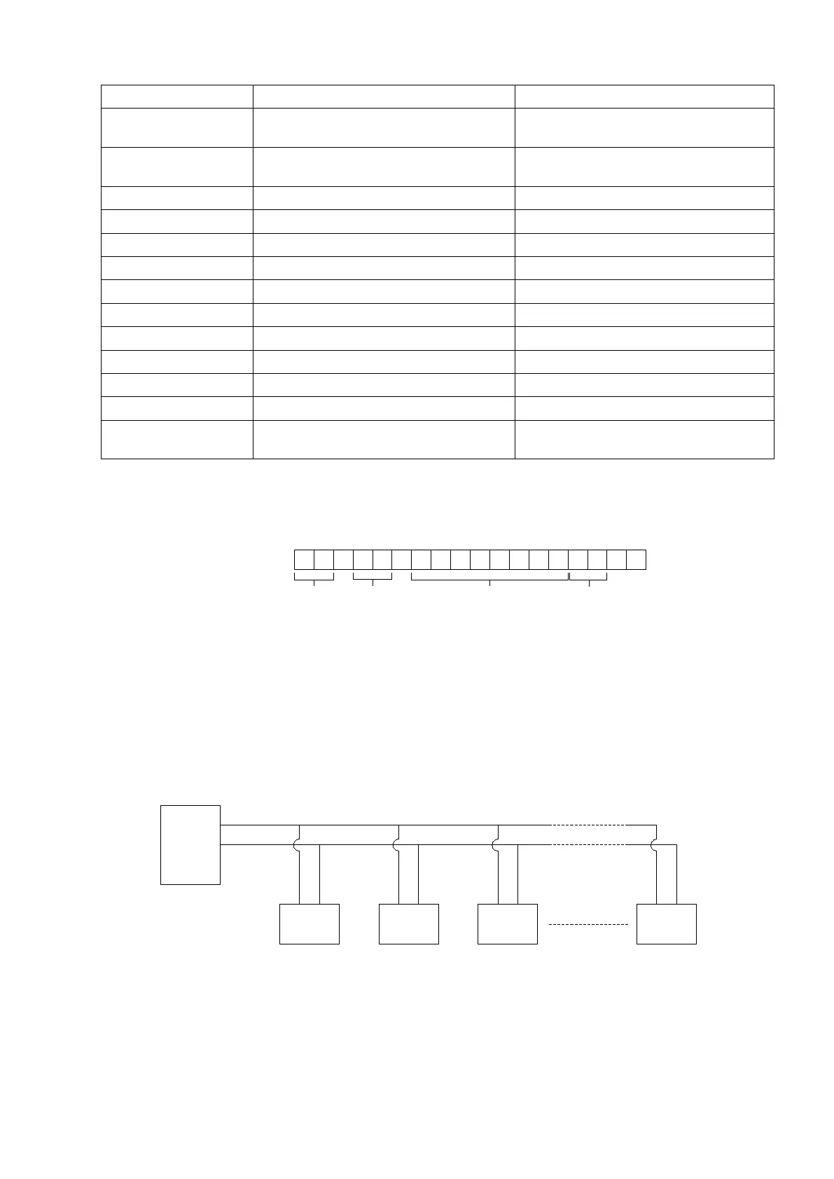
Data format
STATUS 1 : OL = overload, ST = stable, US = unstable
STATUS 2 : NT = net weight, GS = gross weight
WEIGHING DATA : A stream of eight bytes consisting of "0" to "9",
negative sign "-", positive sign "+", space " " and decimal point.
UNIT : kg = kilogram, t = ton
8.3.4 RS485 COMMUNICATION
When the RS485 option is fitted multi-drop communications is possible to allow a single PC to communicate
with up to 99 PT200MI indicators for display of weight or configuration.
Note: When multi-drop RS485 communications are to be used and ID = XX is set in the FUNC setting
stage, the ST62 (TERMINATOR) jumper on the main board (bottom left of the BCD board) should be
set to “ON”, a 200Ω impedance matching resistor is added to the communication terminal. This
applies to only the last PT200MI, ID=XX.
, ,
CR LF
STATUS 1
(2 BYTES)
STATUS 2
(2 BYTES)
WEIGHT DATA
(8 BYTES)
UNIT (KG/t)
(2 BYTES)
PT200MI
ID01
PC
PT200MI
ID02
PT200MI
ID03
PT200MI
IDXX
RS485
+
-
+ + + +- - - -
-