PT200MI instruction manual 32
10.0 APPENDIX
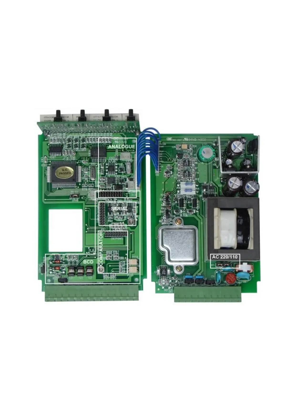
10.0 ACCESSING AND INSTALLING INTERNAL OPTIONS
Supply voltage selection and optional serial interface or output boards are fitted by accessing the
internal circuit boards of the PT200MI. To gain access disconnect the rear connectors and remove the 4
screws in each corner of the rear panel. Inside the circuit boards can be seen retained in guide slots in the
aluminium casing extrusion. Beneath the threaded holes where the rear panel retaining screws attached are
4 more small grub screws. Remove these screws with a small flat blade screw driver. Slide the connected
pair of circuit boards from the casing and place on a clean work surface. The boards can be opened out flat
and care should be taken to avoid damage due to static electricity.
10.1 PT200MI 110V AND 220V SETTING
The supply voltage selection jumpers are on the right hand circuit board just below the transformer. Set
the jumpers both to the left as shown for 220 V ac operation and both to the right for 110 V ac operation.