PT200MI instruction manual 30
8.5 ANALOGUE OUTPUT (OPTIONAL)
Refer to the appendix if installation of the option is required.
Refer to the appendix for instructions on accessing the circuit boards, required for adjustment of
the analogue options.
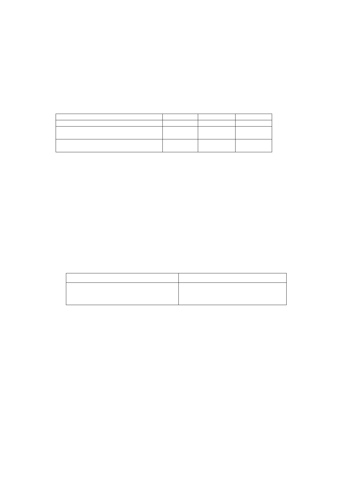
8.5.1 SPECIFICATION
Resolution : 1/10000
Accuracy : 0.5% F.S
Weight output : Gross weight
Output 0~5V 0~20mA 4~20mA
load resistor Min.10 KΩ Max.500Ω Max.500Ω
Output voltage/current when display
value equals to 0
0V 0mA 4mA
Output voltage/current when display
value equals to Max. capacity
5V 20mA 20mA
NOTE: The analogue output is in relation to the absolute value of the display, a negative weight will produce
an output for subtractive batching.
8.5.2 PIN No. DESCRIPTION
(Refer to the rear panel connector diagram on page 7.)
+ : Analogue output +
COM : Analogue output -
* The excitation current available for load cell supply will be reduced to 120mA when the
0~20mA/4~20mA output board is fitted.
8.5.3 ADJUSTING THE ANALOGUE OPTION BOARD
4~20 mA/0~20 mA analogue option 0~5 V analogue option
VR1 Zero adjust
VR2 Span adjust
VR100 Zero adjust
VR101 Span adjust
VR102 No need adjust
To adjust the board to be 0~20mA or 4~20mA refer to the back of the 4~20 mA/0~20 mA analogue
option. There are 2 solder bridges, one should be open and one should be closed. The bridge with
the appropriate label ( 4~20 or 0~20) should be soldered across for the option to operate in this
mode.