5Operation of the PVPM 8
5 Operation of the PVPM
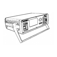
5.1Operating and connection elements
1. Test button for battery charge control (working only with lead acid battery)
2. On/Off switch
3. Status indicator lamps
4. LC display
5. Control buttons
6. Temperature measuring input Pt100 or Pt1000 (depending on model)
7. .Irradiation or combined irradiation and temperature input (depending on model)
8. Serial interface RS-232 to the PC
9. Four-wire measuring connector (voltage)
10. Four-wire measuring connector (current)
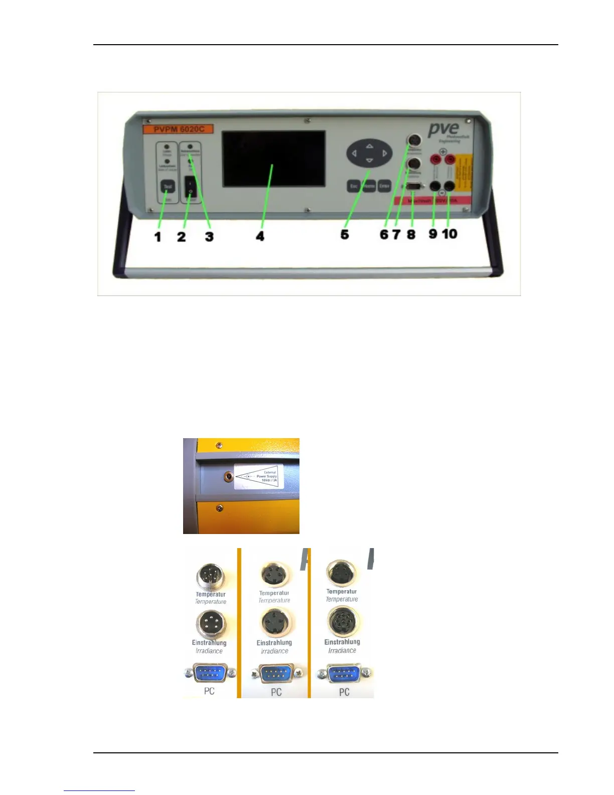
11. External voltage supply/battery charge at left side of the PVPM
Fig.: Sensor connectors until 2003 (left) , 2003 - 2008 (middle), scince 2008 (right )
Operation manual for PVPM devices PV-Engineering GmbH