5Operation of the PVPM 9
5.2General Hints
The PVPM, as nearly all electronic measuring device, can only operate in a defined temperature range (see
appendix). That is why the PVPM should not be exposed to direct sunlight over a longer period of time. Keep
the device in a shady place or protect it from direct sunlight using a sunshade.
The standard version of the PVPM cannot be integrated into other devices or e.g. brackets. It is very important
that the air can move free around the case so that a proper cooling is guaranteed! Only if the PVPM is
completely out of operation (even no charging) it may be stacked.
Attention: Never loosen a measurement cable connection during a measurement! The considerable
dc tensions and currents can cause a light arc which may cause fire, serious injuries and even
death! (see chapter 4)
The front panel of the PVPM is rather rough, but you should handle it with care anyway. To avoid damage of the
front panel please take notice of the following hints:
Do not touch the front panel with a sharp or pointed object. This could force scratches and might even
destroy the foil especially in the regions with switches in the back.
Clean the surface with a soft and damp tissue. Do not use materials that can scratch, especially on the
cover of the display. A scratched display cover will dramatically affect the display quality.
The case is not water proofed. Do not expose the PVPM directly to influence of water, rain or similar.
For a good measuring quality the sun irradiance during the measurement should be above 500 W/m2.
Measurements are possible below this irradiance value, but less precise and meaningful.
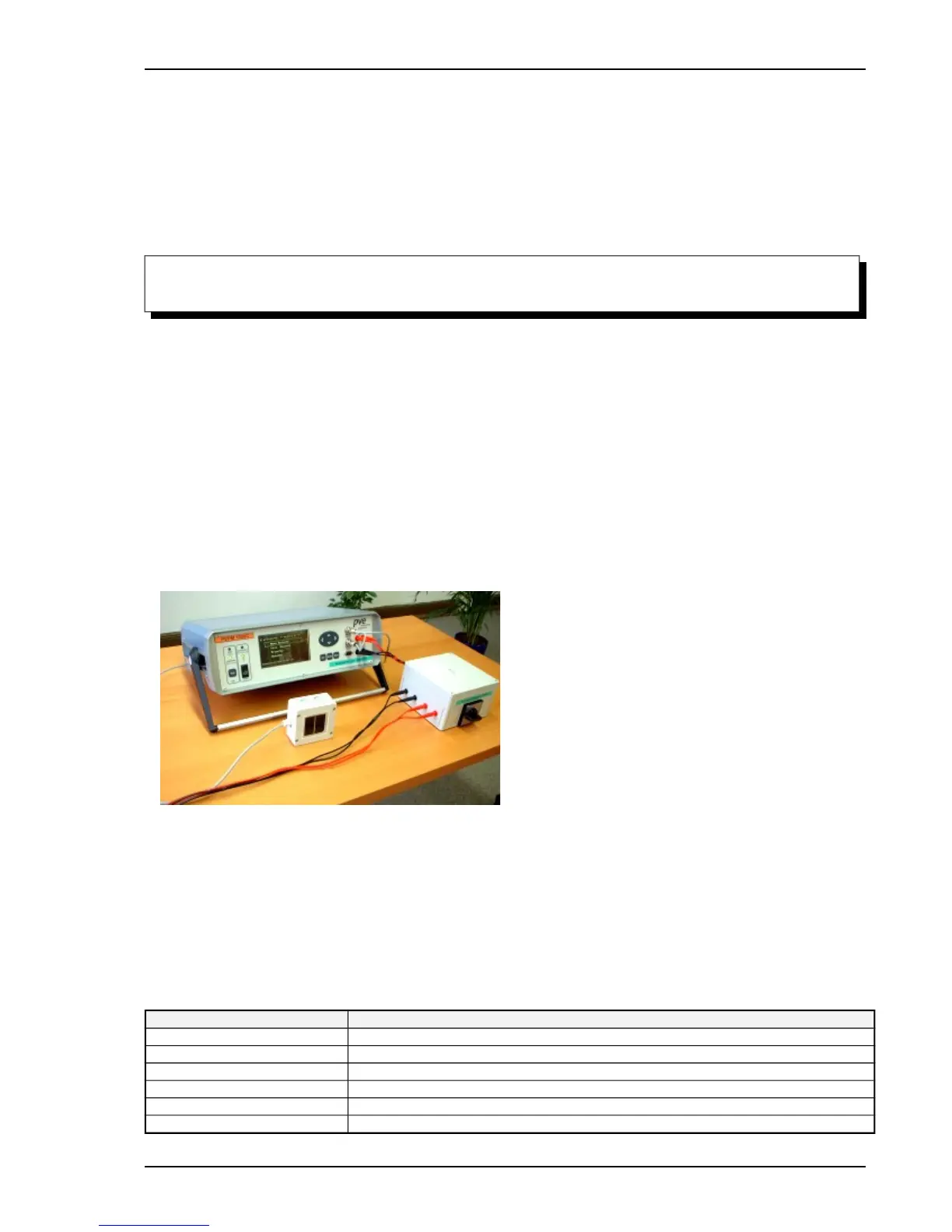
5.3Connecting Peripheral Devices
For an I-V-curve measurement the following components are necessary:
Peak power measuring device PVPM (measurement of I-V-curve, display of results)
Phox irradiance sensor with Pt100/Pt1000 temperature sensor
external security switch 1000V / 32A (see chapter 6)
of course the module to be measured and the cable connection between PV module and PVPM
optional: External PC for the operation of the measurement and evaluation of the measured data
The PVPM is equipped with the following input/output interfaces (you will find all interfaces besides the power
supply at the front panel, they are all marked):
Interface Function
Power supply At the left side of the PVPM, input 16Vdc
Temperature (External) temperature sensor
Irradiance Combined sensor irradiance / Pt1000 temperature
4-wire-measurement Voltage input (module under test)
Current input Current input (module under test)
PC Serial connection to PC (AT Cross cable 9-Pin)
Operation manual for PVPM devices PV-Engineering GmbH